NI myDAQ User Guide | © National Instruments | 9
Connecting Signals
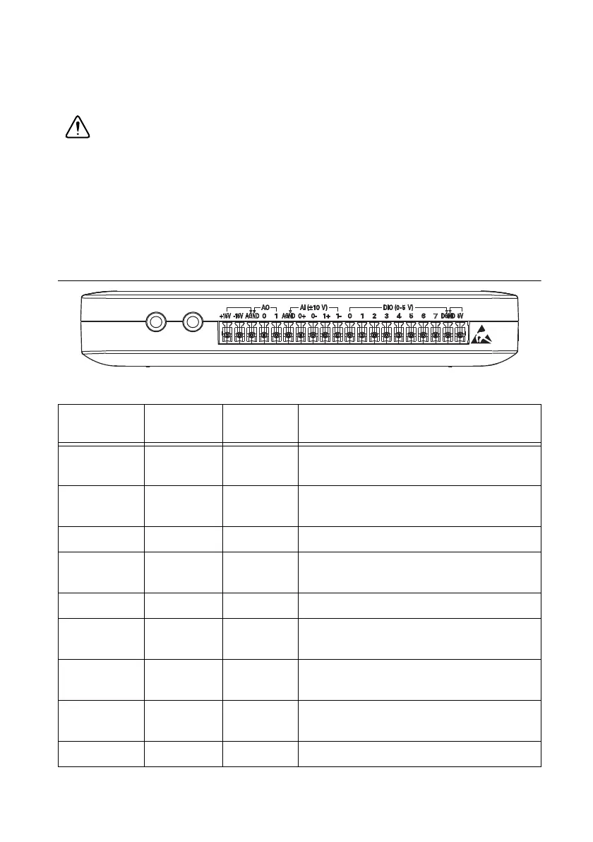
Figure 4 shows the available audio, AI, AO, DIO, GND, and power signals accessed through the
3.5 mm audio jacks and screw terminal connections. Refer to Table 1 for descriptions of these
signals.
Cautions Signal wires must be securely affixed and screwed down in the screw
terminal connector to ensure proper connection.
To ensure the specified EMC performance:
• The length of any wire or cable connected to the 20-pin screw terminal
connector must be no longer than 0.3 m (1 ft).
• The length of any wire or cable connected to the Audio or DMM ports must be
no longer than 3 m (10 ft).
Figure 4. NI myDAQ 20-Position Screw Terminal I/O Connector
Table 1. Screw Terminal Signal Descriptions
Signal
Name
Reference Direction Description
AUDIO IN — Input Audio Input—Left and right audio inputs
on a stereo connector
AUDIO OUT — Output Audio Output—Left and right audio
outputs on a stereo connector
+15V/-15V AGND Output +15 V/-15 V power supplies
AGND — — Analog Ground—Reference terminal for
AI, AO, +15 V, and -15 V
AO 0/AO 1 AGND Output Analog Output Channels 0 and 1
AI 0+/AI 0-;
AI 1+/AI 1-
AGND Input Analog Input Channels 0 and 1
DIO <0..7> DGND Input or
Output
Digital I/O Signals—General-purpose
digital lines or counter signals
DGND — — Digital Ground—Reference for the DIO
lines and the +5 V supply
5V DGND Output 5 V power supply