28 | ni.com | NI myDAQ User Guide
Example: Measuring Signals Using the NI ELVISmx
Oscilloscope Express VI with NI myDAQ
Complete the following steps to use the NI ELVISmx Oscilloscope to measure a signal.
Note For more information on grounding the signals, refer to the Connecting
Analog Input Signals section.
1. Launch LabVIEW.
2. In the Getting Started window, click Blank VI. A blank VI opens. Select Window»Show
Block Diagram to open the VI block diagram.
Tip You can also open the block diagram from the VI front panel by pressing
<Ctrl-E>.
3. Right-click the block diagram window to open the Functions palette, then select
Measurement I/O»NI ELVISmx to open the ELVISmx Express VI palette.
4. Select the NI ELVISmx Oscilloscope Express VI from the VI palette and place it on the
block diagram. The NI ELVISmx Oscilloscope configuration window opens.
5. Connect the signal(s) you want to measure to the connector(s) on the side of the NI myDAQ
device.
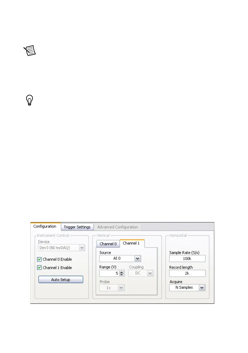
6. On the Configuration tab of the configuration window, select to measure Channel 0,
Channel 1, or both. Select the Channel 0 Enable checkbox to measure Channel 0. Select
the Channel 1 Enable checkbox to measure Channel 1. Select the Channel 0 Enable and
Channel 1 Enable checkboxes to measure both channels.
7. If necessary, click the Auto Setup button to automatically configure the oscilloscope
parameters to acquire the signal, or explicitly set the Sample Rate and Record Length.
You can also configure the measurement to acquire N samples or acquire Continuously.
If necessary, adjust the controls to stabilize the signal in the graph.
8. Click OK on the configuration window front panel.