Appendix A Device-Specific Information
E Series User Manual A-30 ni.com
User <1..2>
The User <1..2> signals connect directly from a screw terminal to a BNC.
They allow you to use a BNC connector for a digital or timing I/O signal of
your choice. The USER 1 BNC is internally connected to pin 21 and the
USER 2 BNC is internally connected to pin 22 on the 30-pin I/O connector.
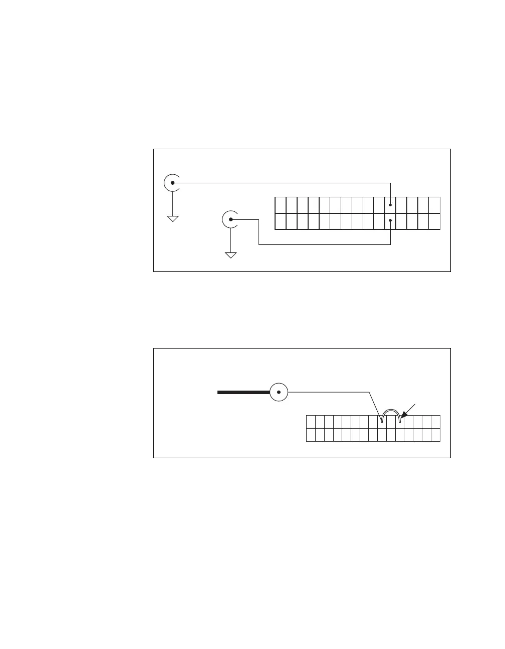
Figure A-30 shows the connection of the User <1..2> BNCs.
Figure A-30. BNC User <1..2> Connection
Figure A-31 shows another example of how to use the User <1..2> BNCs.
To access the Ctr1Out signal from a BNC, connect pin 21 (USER 1) to
pin 17 (CTR 1 OUT) with a wire.
Figure A-31. BNC User <1..2> Example
User 1 BNC
User 2 BNC
Pin 21
Pin 22
30-Pin I/O Connector
D GND
D GND
User 1 BNC
Connector
Pin 21
BNC Cable Internal Connection
Counter 1 Out
Signal
Pin 17
Wire

 Loading...


