20 | ni.com | Getting Started with NI 7340/7350 Controllers and AKD Drives
Step 6: Connect the AC Input Power
Connect the X3 mains supply connector to AC input power. Pins 4 through 7 contain the AC
power signals. The X3 connector also provides signals for an external brake (regen) resistor
(±RB) and DC bus link (–DC). Refer to the AKD Installation Manual for information about
using these terminals.
Note Do not turn on AC power until after you complete Step 7: Connect the Drive
Communication
in the NI UMI and AKD Servo Drive Configuration and Installation
section.
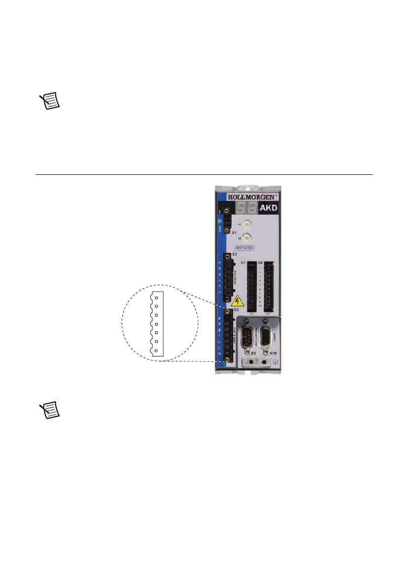
Figure 13 shows the location and pin assignment for the X3 connector.
Figure 13. AKD Servo Drive X3 Connector
AC input power can be connected for either a three-phase or single-phase operation.
Note External filtering and fusing are optionally provided by the user. Refer to the
AKD Installation Manual for information about filter and fuse requirements.
 Loading...