22 | ni.com | Getting Started with NI 7340/7350 Controllers and AKD Drives
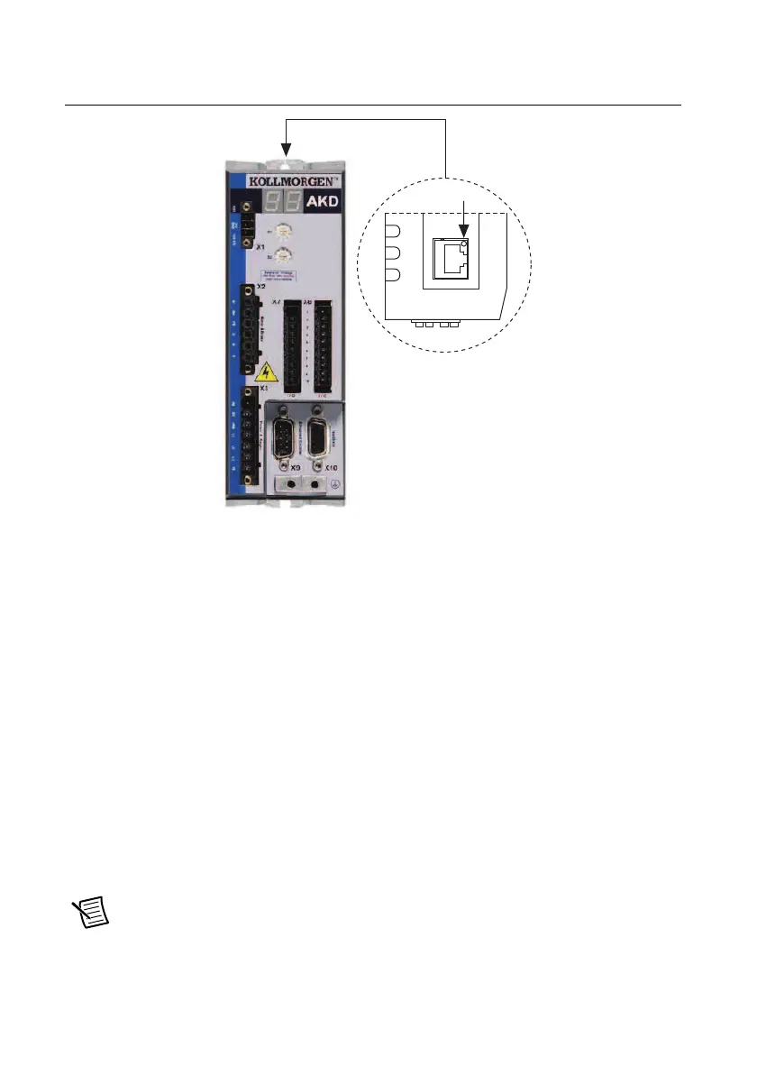
Figure 16 shows the location of the X11 service port on the drive.
Figure 16. AKD Servo Drive X11 Connector
Step 8: Confirm Drive Connections
After all hardware connections have been made complete the following steps to confirm the
AKD hardware setup.
1. Apply AC power.
2. Turn on the +24 V power supply. After logic power is supplied to the drive, the drive
displays the following sequence of flashes in the LED indicators. Figure 9 shows the
location of the LED indicators on the AKD servo drive.
a. – –
b. []
c. Drive IP address, flashed sequentially
d. Drive status, either current operation mode or the fault code if there is a fault
condition. The operation modes are as follows:
• o0—torque mode (current mode)
• o1—velocity mode
• o2—position mode
Note If the drive shows a fault code, click the Clear Faults button on the AKD
WorkBench software toolbar after you install the AKD WorkBench software in
Step
3: Install AKD WorkBench and Configure the Drive
in the Software Installation and
Configuration
section and connect to the drive to clear the fault state. If the fault
 Loading...