Getting Started with NI 7340/7350 Controllers and AKD Drives | © National Instruments | 37
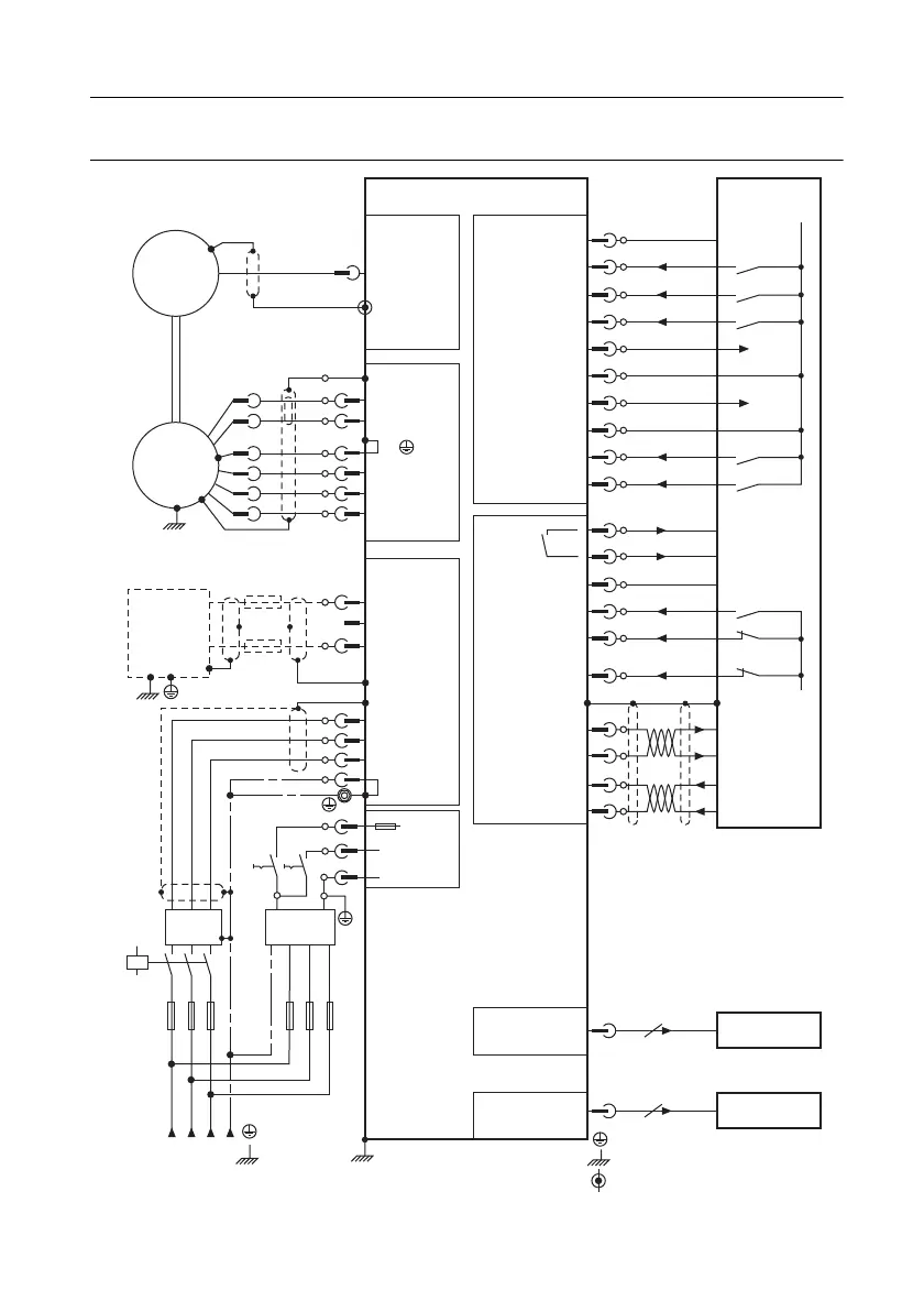
Wiring Diagram
Figure 28. AKD Wiring Diagram
M
Shield Connection Via Plug
X1
1
7
6
5
4
6
5
4
3
2
1
3
2
8
7
9
10
4
3
2
1
5
6
8
7
6
5
4
3
2
1
9
10
1
B–
B+
PE
U1
V1
W1
F
B1
F
B2
F
N1
F
N2
F
N3
F
H1
F
H2
F
H3
3
2
X8
X7X10
X2
X3
Analog–In +
Analog–Out +
DIGITAL–IN5
(PSTOP)
DIGITAL–IN1
DIGITAL–IN7
DIGITAL–IN3
DIGITAL–IN4
DIGITAL–IN2
DIGITAL–OUT1
+
DIGITAL–OUT2
+
DIGITAL–OUT2
–
DIGITAL–OUT1
–
DIGITAL–IN6
(NSTOP)
AGND
DGND
DGND
Fault
Feedback
Thermal Control
Included
Reference Safety Instructions
and Use As Directed
– Br
– RB
– DC
L1
L2
L3
PE
+ 24V
STO
GND
+ RB
+
(
+ DC
)
+ Br
PE
U
V
W
ENABLE
Analog–In –
+
Referred to
I/O–GND
I/O–GND
Emergency
Stop Circuit
Digital1
Digital2
+/– 10V Speed
Setpoint
+/– 10V
+ 24V Referred
to I/O GND
+ 24V Referred
to I/O GND
I/O–GND
Control
+
Tachometer
Voltage
+
–
–
Chassis Ground Connection (Panel)
PE–Connection (Protective Earth)
Feedback
Regeneration
Resistor
Filter
Supply Unit
24V DC
L1 L2 L3 PE
Mains
Contactor
+–
X9
Encoder
Emulation
9
Encoder
Evaluation
X11
TCP/IP
Service
8
 Loading...