6 | ni.com | NI PXIe-4302/4303 and TB-4302/4302C
4. Run the shielded signal wires through the strain-relief opening.
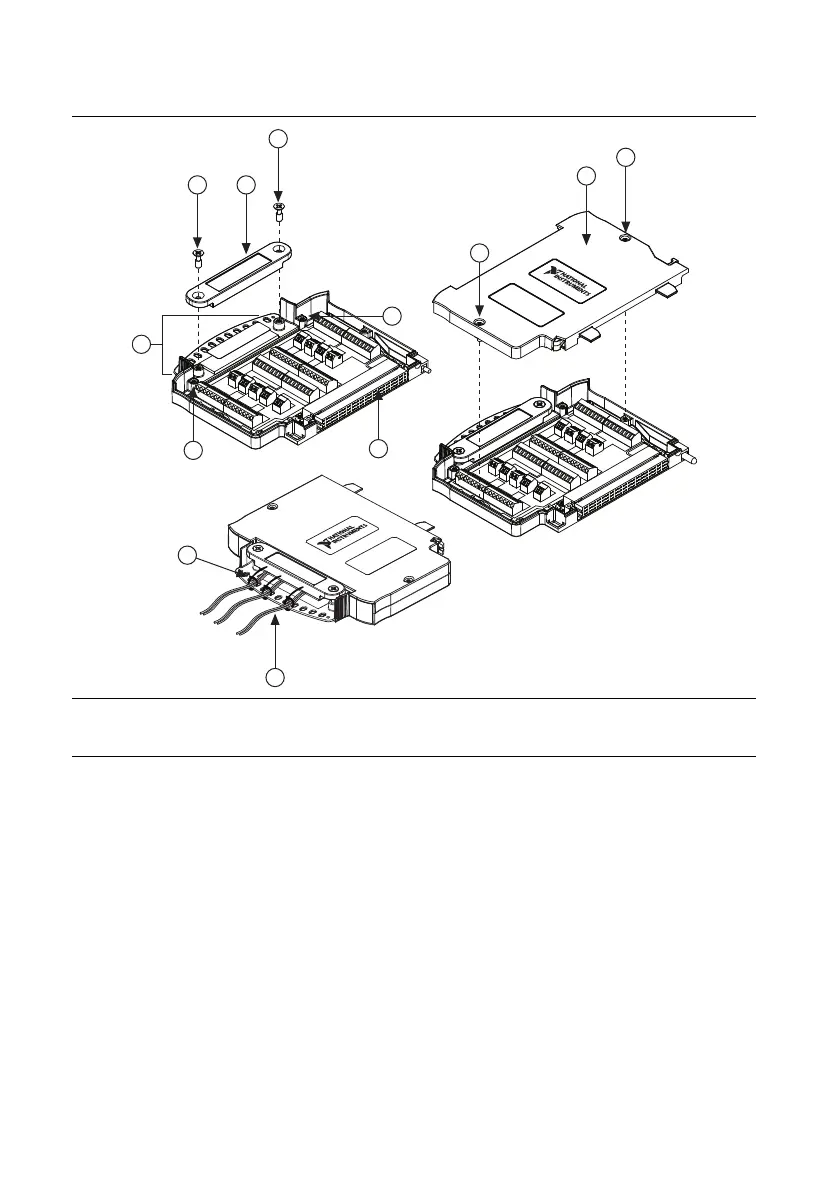
Figure 3. TB-4302/4302C Parts Locator Diagram
5. Insert the stripped end of the shielded signal wires fully into the appropriate terminal. Refer
to the label next to each screw terminal to determine the function of the terminal. The
NI PXIe-4302/4303 User Manual provides more detailed wiring information. Make sure no
exposed wire extends past the screw terminal. Exposed wire increases the risk of a short
circuit that can cause circuit failure.
1 Strain-Relief Screws
2 Strain-Relief Bar
3 Tie Wrap Holes
4 Ground Lugs
5 Terminal Block to Module Connector
6 Captive Top Cover Screws
7 Top Cover
8 Tie Wraps
9 Shielded Signal Wires
3
1 2
1
4
6
7
6
5
4
8
9
 Loading...