8 | ni.com | NI PXIe-4302/4303 and TB-4302/4302C
Caution Any wires connected to the ground must be sufficiently insulated from
high voltage.
7. Use the ground lugs to attach a shield wire to the ground.
Note Refer to the NI PXIe-4302/4303 User Manual for details about shielding the
signals.
8. Reinstall the strain-relief bar and tighten the strain-relief screws.
9. Use tie wraps to connect the shielded signal wires to the tie-wrap holes for additional strain
relief when necessary.
10. Reinstall the top cover and tighten the captive top cover screws.
Note For information about sensors, go to ni.com/sensors.
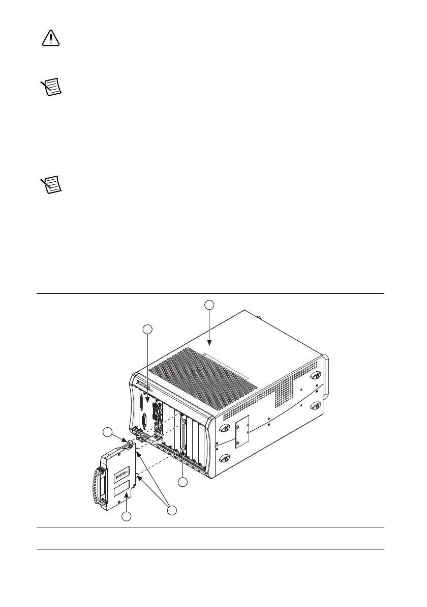
Install the Terminal Block
Refer to Figure 6 to install the terminal block on the module while completing the following
steps:
1. Move the TB-4302/4302C into position in front of the NI PXIe-4302/4303 and engage the
alignment feature with the guide on the associated module.
Figure 6. Installing the TB-4302/4302C on the NI PXIe-4302/4303 Module
1 PXIe Controller
2 PXIe Chassis
3 Mounting Screw
4 TB-4302/4302C Terminal Block
5 NI PXIe-4302/4303 Module
6 Alignment Feature
NI PXIe-1062Q
2
1
3
6
4
5
C
O
O
LI
N
G
C
LE
AR
A
N
C
E
AN
D
FA
N
FIL
TE
R
M
AIN
T
EN
AN
C
E
R
EQ
U
I
R
ED
.
S
EE M
AN
UAL.
C
O
O
L
IN
G
C
L
E
A
R
A
NC
E
A
N
D
F
A
N
F
I
LT
ER
M
A
I
NT
E
N
A
N
CE
R
E
Q
U
IRE
D.
S
E
E
M
A
N
UA
L.
 Loading...