NI PXIe-4302/4303 and TB-4302/4302C | © National Instruments | 9
2. Attach the TB-4302/4302C to the NI PXIe-4302/4303 module by pushing the terminal
block straight into the module. A spring mechanism will lock in the bottom of the terminal
block.
3. Tighten the mounting screw at the top of the TB-4302/4302C to attach it to the
NI PXIe-4302/4303 module.
Note For safety purposes and to prevent damage to equipment when high voltages
are present, all NI PXIe-4302/4303 modules and TB-4302/4302C terminal blocks are
keyed to prevent connection between incompatible terminal blocks, modules, and/or
cables.
4. Power on the chassis.
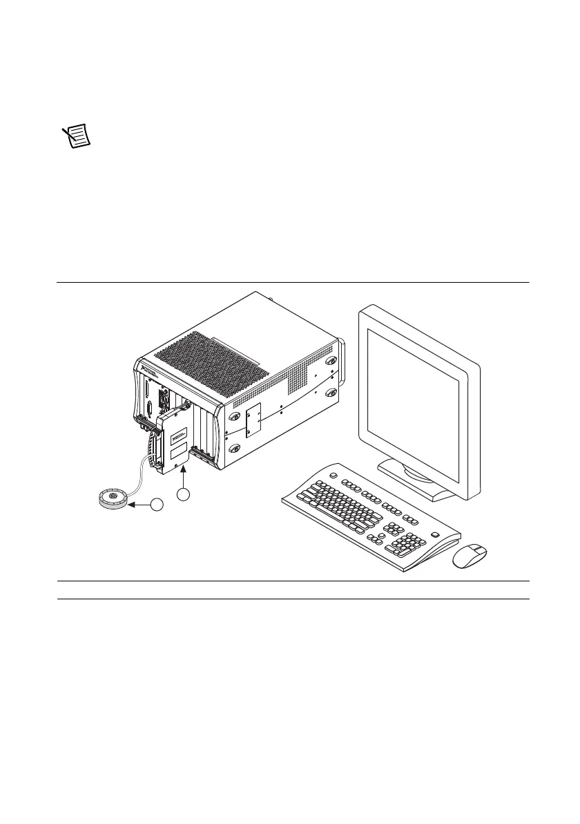
Figure 7 shows an example NI PXIe-4302/4303 system setup.
Figure 7. Sample NI PXIe-4302/4303 System
1 Terminal Block 2 Signal Input
NI PXIe-1
0
6
2
Q
1
COOL
I
N
G
CL
E
A
RA
NC
E
A
ND FA
N
F
I
L
T
ER
MA
I
NT
EN
A
N
CE
R
E
Q
UIRE
D
.
S
EE
MA
NU
A
L
.
COOL
I
NG
CL
E
A
RA
NC
E
A
ND F
A
N
FIL
TE
R
M
AI
NTE
N
A
N
C
E
REQU
IR
ED
.
S
EE
MA
N
UA
L
.
2
 Loading...