NI PXIe-4302/4303 and TB-4302/4302C | © National Instruments | 5
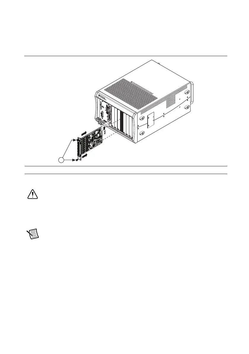
7. Slide the module along the guides until it reaches the rear connector then seat the module
by pushing the front panel until it is flush with the front panel of the chassis.
8. Secure the module to the chassis using the front-panel captive screws, shown in Figure 2.
Tighten the screws to 0.31 N · m (2.7 lb · in.).
Figure 2. Installing NI PXIe-4302/4303 Modules
Connect the Signals
Caution For EMC compliance, operate this product with shielded cables and
accessories.
To connect signals to the terminal block, refer to Figures 3 and, 4 or 5 while completing the
following steps:
Note You can find the pinout names and locations in Measurement & Automation
Explorer (MAX) at any time by right-clicking the device name under Devices and
Interfaces and selecting Device Pinouts.
1. Loosen the captive top cover screws and remove the top cover.
2. Loosen the strain-relief screws and remove the strain-relief bar.
3. Prepare the shielded signal wire by stripping the insulation no more than 7 mm (0.28 in.).
1Captive Screws
NI
PX
I
e
-1062Q
CO
O
L
I
NG
CL
E
A
RA
NCE
A
ND
F
A
N
F
I
L
T
E
R
MA
I
NTE
NA
NCE
RE
Q
U
I
RE
D
.
S
E
E
MA
NU
A
L
.
1

 Loading...