Dantec Keypoint Focus
29
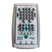
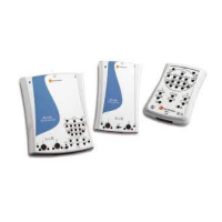
Amplifier Input Connectors – Common Array
The green light (LED) indicates the results of the
impedance test as described below.
LED Status
All LEDs Off
Constantly lit LEDs
Result
Acceptable Impedance
High Impedance
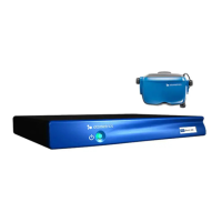
Amplifier Input Connectors – Head Array (Montage)
The head array electrode connectors are labeled
according to the International 10-20 System of
Electrode Placement.
The green light (LED) indicates the results of the
impedance test. –See the LED Status and Results
description under Amplifier Input Connectors –
Common Array above.
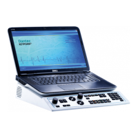
Patient Ground Connector / Indicator
Connect the patient's ground electrode to the green
connector.
The green light (LED) indicates the results of the
impedance test. –See the LED Status and Results
description under the Amplifier Input Connectors –
Common Array above.
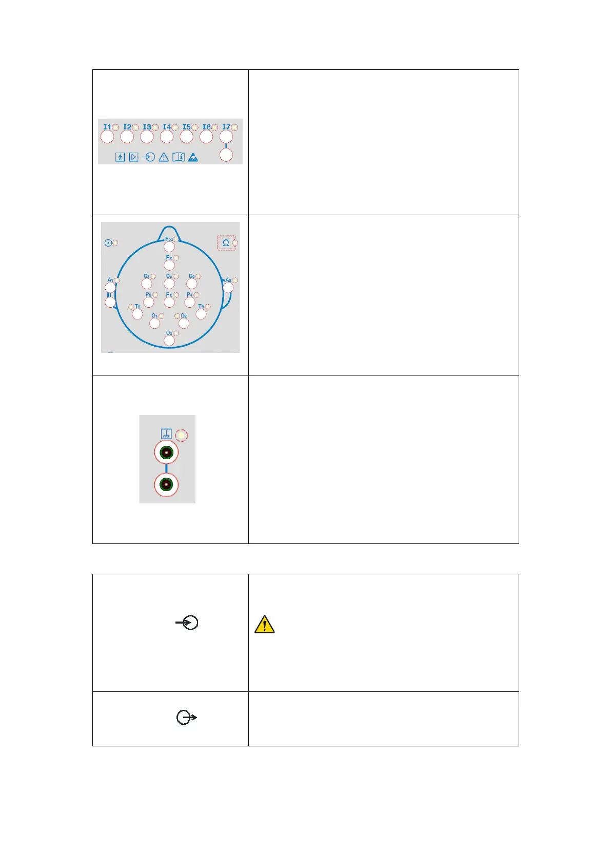
HS Link Input Connector
Main Unit - Side Panel
WARNING Due to risk of ele
operator and/or patient must not directly or indirectly
touch the metal shield on the LINK cable attached to the
rear of the amplifier.
HS Link Output Connector
Not Available
For future use of extra module connection.