Instructions for Use XLTEK Protektor32
48
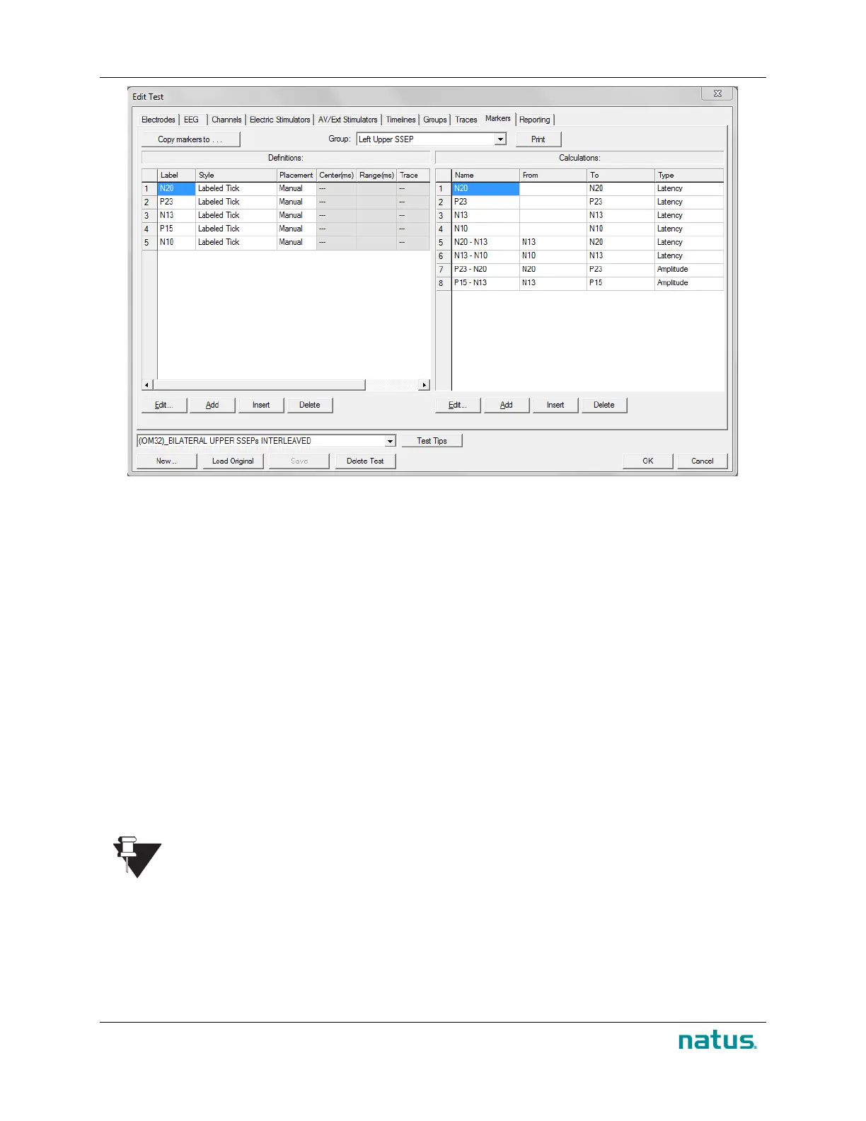
To Set Up the Marker Definitions Table:
1. Click the Append button to add a row to the marker definitions table.
2. Right-click the cell in the Style column and select from:
• Amplitude
• Cursor
• Latency Cursor
• Tick with Latency Value
• Tick with Amplitude Value
• Tick with Latency and Amplitude Values
• Labeled Tick with Latency Value
3. Then right-click the cell in the Placement column and select from:
• Manual
• Peak
• Trough
When selecting Peak and Trough, enter the appropriate values in the From (ms) and To (ms)
columns.
Note that five milliseconds on either side of the expected latency of the waveform are
generally acceptable.
4. Enter the values in the From (ms) and To (ms) column’s cell to indicate when the marker begins
and ends. The default value is 0 ms and 15 ms respectively.
5. To attach the marker to a specific trace, right-click the cell in the Trace column and select the
trace from the menu displayed.
 Loading...