32 Installing the Water Heater
Wiring Connection Table
Terminal Wiring Connection
Signal1
12 V
Contacts for wireless push
button or motion sensor
connection
Signal
GND
5 V
Signal2
(Not polarity
sensitive)
Push Button Switch Contact #1
Push Button Switch Contact #2
Sensor I
Contacts for temperature
sensor connection
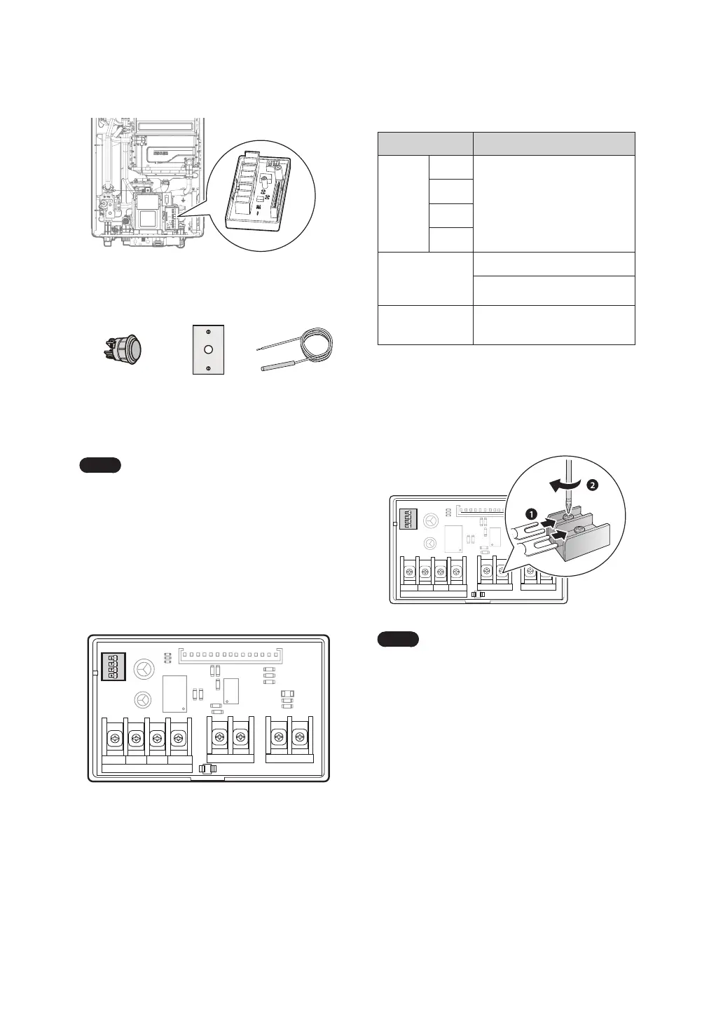
Connecting Wired Switches
Refer to the following diagrams to connect a wired
switch, or multiple wired switches to the HotButton
controller.
CE1
CE2
U1
C1
C2
C7
R6
PC1
12 V 5 V SIGNAL
SIGNAL 1
GND
R5
R9
R8
C3
R1
R2
R7
D1
CON3
CON5
CON2
CON1
SIGNAL 2
SENSOR I
RA1
1 2 3 4
ON
SW1
Note
●
Multiple wired switches may be
connected to the same terminal
contacts.
●
Use spade connectors at the end of the
cables to securely install the cables to
the terminal contacts.
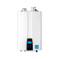
Included Item
HotButton Controller
Items Not Included
Push Button
Switch
(#GXXX001426)
Wall
Plate
(#GXXX001427)
Temperature
Sensor
(#GXXX001640)
Note
In addition to activating the HotButton
using push buttons, recirculation can
also be started through the NaviLink
app if the optional NaviLink WiFi
control system has been installed.
Device Layout
Refer to the following diagram for the product
layout.
CE1
CE2
U1
C1
C2
C7
R6
PC1
12 V 5 V SIGNAL
SIGNAL 1
GND
R5
R9
R8
C3
R1
R2
R7
D1
CON3
CON5
CON2
CON1
SIGNAL 2
SENSOR I
RA1
1 2 3 4
ON
SW1
* SIGNAL1 contacts are for optional wireless push buttons
or motion sensor accessories.
** SENSOR I contacts are connected with a piece of
metal plate by default. Remove the metal plate before
connecting a temperature sensor to the circuit board.
 Loading...