System Details 57
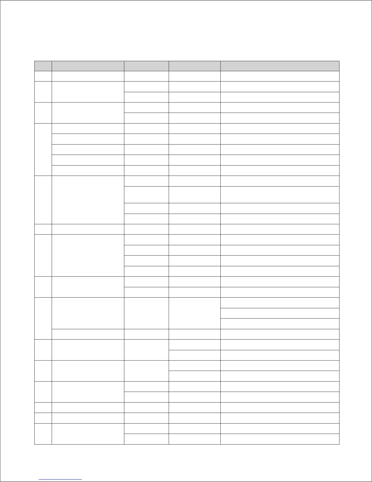
Point Function Wire Color Normal Value Check
A High Temperature Limit Switch BLACK-BLACK DC 0 V Normally Shorted. Confirm RMS voltage.
B APS
RED-BLACK DC 5 V Confirm steady voltage.
WHITE-BLACK DC 0.3~4.5 V Voltage changes according to the APS operation.
C Flow Sensor
RED-BLACK DC 12 V Confirm steady voltage.
WHITE-BLACK PULSE Check Pulse.
D
Cold Water-1 BLUE-BLUE DC 0~5 V Voltage changes according to temperature.
Hot Water-2 BLUE-BLUE DC 0~5 V Voltage changes according to temperature.
Cold Water-1 BLUE-BLUE DC 0~5 V Voltage changes according to temperature.
Hot Water-2 BLUE-BLUE DC 0~5 V Voltage changes according to temperature.
Exhaust Sensor BLUE-BLUE DC 0~5 V Voltage changes according to temperature.
E Water Adjust / Mixing Valve
RED-BLACK DC 12 V Confirm steady voltage.
WHITE-BLACK DC 0-5V
Voltage changes according to the Mixing Valve
position.
BLUE-BROWN
ORANGE-YELLOW PULSE Check Pulse.
F Flame Rod BLACK 0~10 uA Measure the current when the burner is operating.
G Fan Motor
BLACK-RED DC 127V~184 V Confirm steady voltage.
BLACK-YELLOW DC 15 V Confirm steady voltage.
BLACK-ORANGE DC 0~7.5 V Voltage changes relative to fan operation.
BLACK-WHITE 0 rpm~6500 rpm Check PULSE.
H Pump
YELLOW-WHITE * ON : AC 96 ~138 V Confirm voltage as operating.
* OFF : 0V
I
Power Input WHITE-BLACK AC 97~138 V
* Confirm appropriate power source.
* Confirm the FUSE.
* Confirm the circuit breaker.
Ground Wire GREEN-YELLOW Ground Wire Check for properly grounded wire.
J Dual Venturi BROWN-BLUE
* ON : AC 95~120V Confirm voltage relative to operation.
* OFF : 0V
K Igniter BLUE-BLUE
* ON : AC 97~138 V Confirm voltage when the unit is igniting.
* OFF : 0V
L Gas Valve
RED-YELLOW DC 22~24 V Confirm voltage as the Main Gas Valve 1 is operating.
WHITE-RED DC 22~24 V Confirm voltage as the Main Gas Valve 2 is operating.
M Front Panel BLACK
N Comfort Air+ BLACK
O External Pump
BLACK * ON : AC 96 ~138 V Confirm voltage as operating.
* OFF : 0V
 Loading...