System Details 21
1. Water Flow Begins
●
Water Flow Sensor sends pulses to the PCB when it registers
water flow.
●
PCB senses flow greater than 0.53 GPM (approximate).
●
Firing Sequence begins.
2. Firing Sequence
●
PCB monitors Inlet / Outlet water temperature, temperature
set point, and water flow rate.
●
Fan Motor activates Purge Cycle in the combustion chamber.
●
Spark igniter begins ignition process.
●
Main Gas control valve opens to minimum fire rate.
●
Flame rod ignition confirms ignition and initial combustion.
●
Spark igniter stops ignition process.
3. Normal Operation
●
PCB monitors flame rod, fan motor frequency, outlet water
temperature, PCB temperature set point and water flow rate.
●
Main Gas control valve modulates gas input to required
firing rate.
●
Combustion fan speed is adjusted for the required firing rate.
●
Water adjustment valve is adjusted as needed.
4. Shut-down Sequence
●
PCB senses flow rate less than 0.48 GPM (approximate).
●
Main Gas Control valve closes.
●
Water adjustment valve resets to standby position.
●
Fan Motor activates Purge Cycle in the combustion chamber
at low speed.
5. Standby Mode
●
PCB monitors water temperature and remote controls.
●
Freeze protection is activated as needed.
4.3 Setting the DIP Switches
The water heater has two DIP switch locations: on the main circuit
board (PCB) and on the front panel. Each location has two sets
of DIP switches that control the functionality of the water heater.
Set the DIP switches appropriately, based on the installation
environment and the gas type.
4.3.1 Setting the DIP Switches
The water heater has two DIP switch locations: on the main circuit
board (PCB) and on the front panel. Each location has two sets
of DIP switches that control the functionality of the water heater.
Set the DIP switches appropriately, based on the installation
environment.
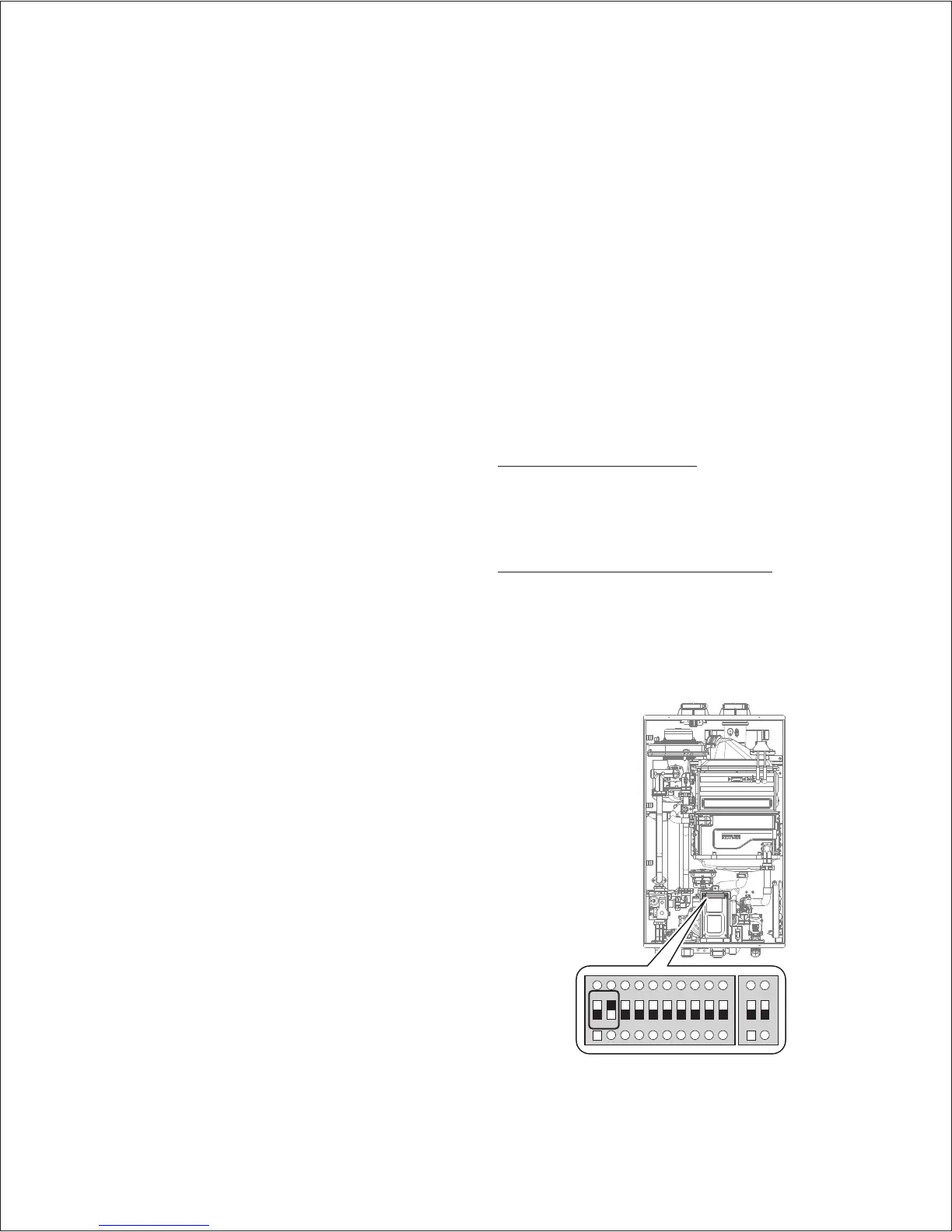
Circuit Board DIP Switches
The two sets of DIP switches on the circuit board configure the
water heater’s model settings. These configurations are set at the
factory and should not be changed.
Setting the Front Panel DIP Switches
The two sets of DIP switches on the front panel configure the water
heater’s pump & recirculation, display, well pump, storage tank &
solar system, lime alarm, high altitude, Cascade Venting and Gas
Type settings. Some of these configurations are set at the factory
and should not be changed. The following tables describe the
functions of the DIP switches and their settings:
1 2 3 4 5 6 7 8 9 10
ON ON
 Loading...