Section 2: Components
18 Product Description
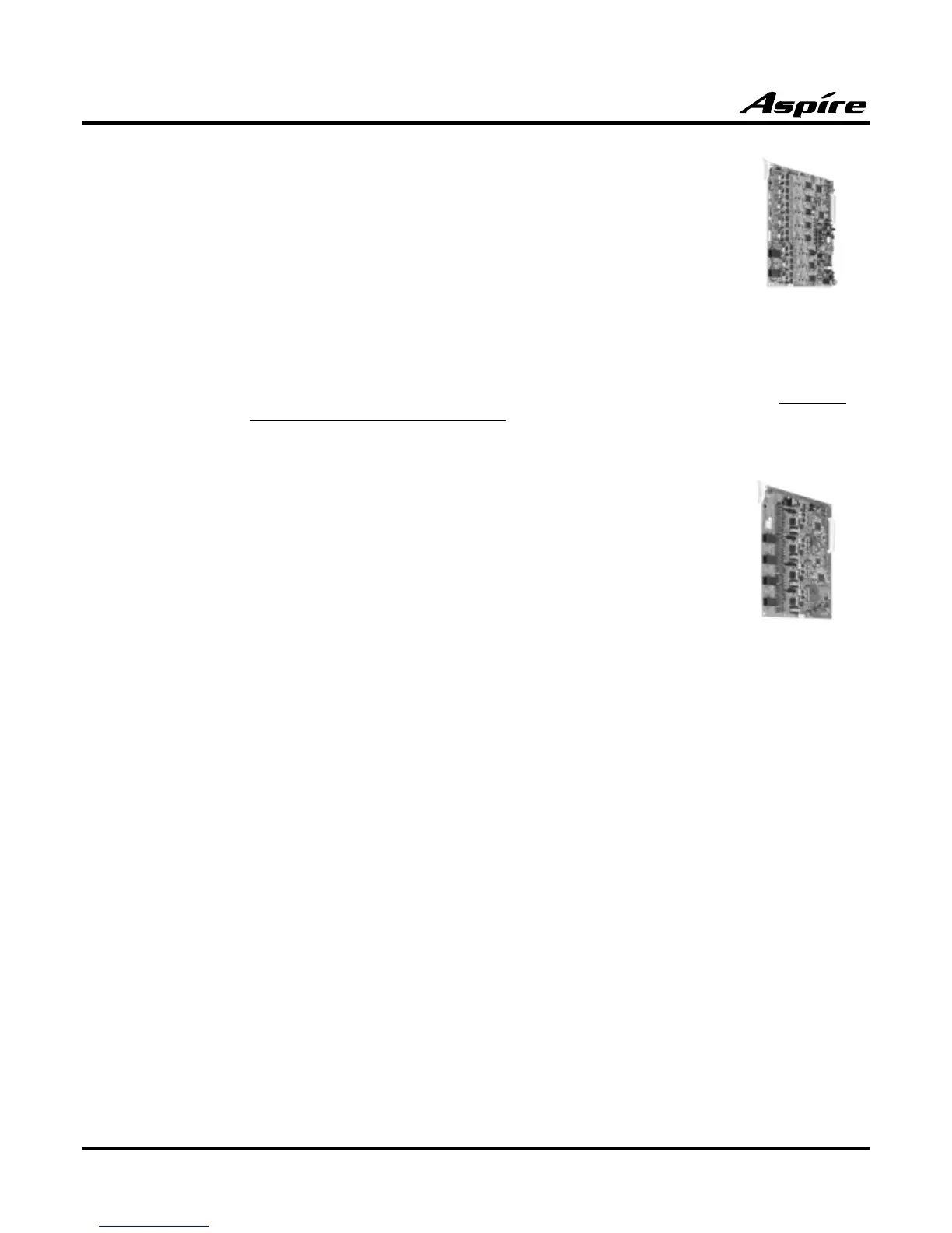
8 DID/OPX (8DIOPU) Card — P/N 0891012
The 8DIOPU PCB supports the analog DID and single line telephone inter-
face functions (such as Off-Premise Extension). The function type is assigned
in programming for each port. The circuit types, however, should be grouped
together. For example, with 3 DID circuits and 1 OPX circuit, they should be
grouped as DID, DID, DID and OPX and not DID, DID, OPX and DID.
The DIOPU PCB provides:
● 8 DID trunk circuits
● 8 DID trunk status LEDs
● 1 PCB status LED
● 1 run/block switch
The CN3 and CN5 connectors each provide connection to 4 analog DID trunk ports, which are
polarity sensitive (tip to tip, ring to ring). The OPX circuits, however, are not polarity sensitive.
The DIOPU requires one universal slot, with 15 maximum PCBs per system.
4 E&M Tie Line Card (4TLIU) — P/N 0891011
The 4TLIU Tie Line PCB is an out band dial type analog tie line inter-
face PCB. The PCB supports system connections to either 2-wire (four
lead, tip/ring) or 4-wire (eight lead, tip/ring/tip 1/ring 1) E&M signalling
tie lines (determined in Program 10-03). Using switches on the PCB,
each circuit type can be set as Type I, II, III, IV, or V. Each PCB provides:
● 4 4-circuit tie line interfaces
● 4 tie line status LEDs
● 1 PCB status LED
● 1 run/block switch
● 2 straps and 1 switch per circuit to determine the circuit type
A maximum of 15 PCBs per system are allowed, providing 60 tie line trunks and it can be plugged
into any universal slot.
2 BRI Card (2BRIU)— P/N 0891006
The 2BRIU provides:
● 2 2-Channel Circuits (2B + D) configured as T-Bus or S-Bus
● 64 Kb/s Clear B-Channel and 16 Kb/s D-Channel
● 2 trunk/extension status LEDs
● 1 PCB status LED
● 1 run/block switch
The BRI Interface PCB uses a single universal slot. A maximum of 15 2BRIU PCBs can be installed.
Each PCB connects to the network via an NTI Network Termination. With the maximum number of
PCBs installed, the following can be provided:
● The 2BRI provides 30 BRI circuits and 60 BRI channels.
The trunk circuit can be connected to either an ISDN trunk or ISDN telephone set, depending on the
SW102 through SW202 switch settings. When used for S-Bus, a maximum of 8 ISDN terminals can
be connected to each circuit.
Two ISDN telephone circuits (1-2) are supplied with DC power from the Aspire system.
 Loading...