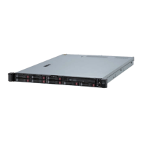
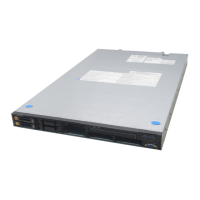
1-8 System Overview
A
B
C
D
E
A
– External SCSI Device #1
Output Port
External SCSI output port for tape drive #1.
B
– AC Input Plug
AC input plug for 75-watt power supply.
C
– External SCSI Device #1
Input Port
External SCSI input port for tape drive #1.
D
– External SCSI Device #2
Input Port
External SCSI input port for tape drive #2.
E
– External SCSI Device #2
Output Port
External SCSI output port for tape drive #2.
Figure 1-7. Optional Tape Drive Bay Kit
Rear Chassis Features and Controls
Status LED Indicator Descriptions
Table 1-1 lists the system status LED indicators along with a description of each LED
indicator. Table 1-2 lists the disk drive status LED panel indicators along with a
description of each LED indicator. Table 1-3 lists the CPU module status LED
indicators along with a description of each LED indicator. Table 1-4 lists the PCI
module status LED indicators along with a description of each LED indicator. Table 1-5
lists the PCI adapter-slot status indicators along with a description of each LED
indicator. Table 1-6 lists the power supply status LED panel indicators along with a
description of each LED indicator.
The access LED indicators for the CD-ROM drive and the diskette drive light when
access is being made to the media in the drive.

 Loading...


