7-4
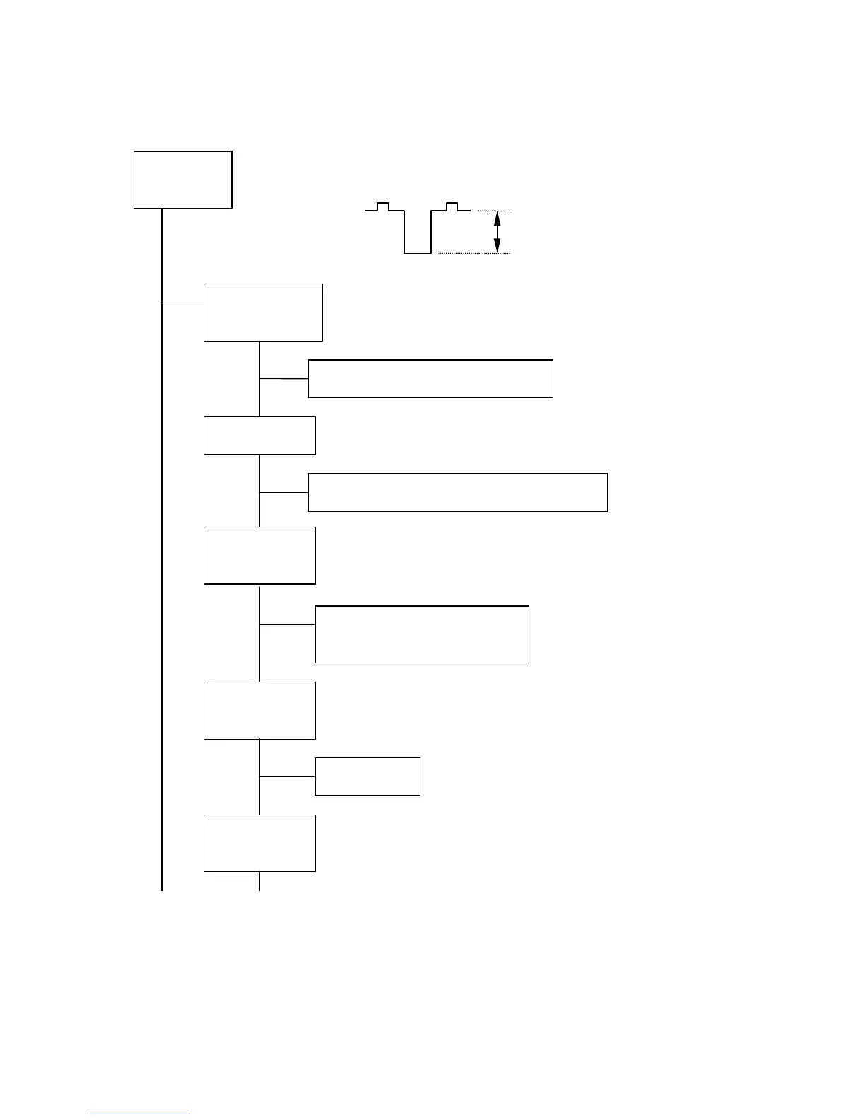
2. ABNORMAL VIDEO ON CRT SCREEN (too dark or too bright)
* Input 1/4 window pattern.
Set up BRIGHTNESS: preset, CONTRAST:max. and R/G/B control:all max. at OSM menu.
Measure R/G/B video outputs at TP-R, TP-G and TP-B on the CRT PWB (PWE-567C).
Normally, R/G/B video output voltages are approx. 45Vp-p with 1/4 window pattern input
when the contrast control of the OSM menu is MAX.
NG
Measure the video output at IC721 pins 6(R), 14(G) and 4(B) on VIDEO
PWB (PWE-567A).
Normally, the wave form is same as upon figure.
OK
NG
Measure the voltage at CNP 3 on the VIDEO PWB(PWE-567A).
NG
OK
1) Check the voltage at C726 on the VIDEO PWB(PWE-567A). The voltage
is approx. 9.1V
DC
.
2) Check the voltage at R728 (reverse of ZD721) on the VIDEO PWB
(PWE-567A). The voltage is approx. 12V
DC
.
NG
OK
Measure the video input at IC721 pins 8(R), 12(G) and 2(B) on VIDEO PWB
(PWE-567A). The voltage is approx. 5Vp-p.
OK
NG
Measure the video output at IC711 pins 32(R), 29(G) and 35(B) on VIDEO
PWB (PWE-567A). The voltage is approx. 3Vp-p.
CONTINUE 1 CONTINUE 2
Check R/G/B
video output
45 Vp-p
Check IC721
output (VIDEO)
C729R/G/B failure, or CN-SG Failure.
Check 80V line
CN-P failure, or check SW-REG (see item 13)
Check Vbb line
and 12V line
1) ZD721, C726, R728 failure.
2) CN-AF failure.
Check IC721
input (VIDEO)
IC721 failure.
Check IC711
output (VIDEO)