8-4
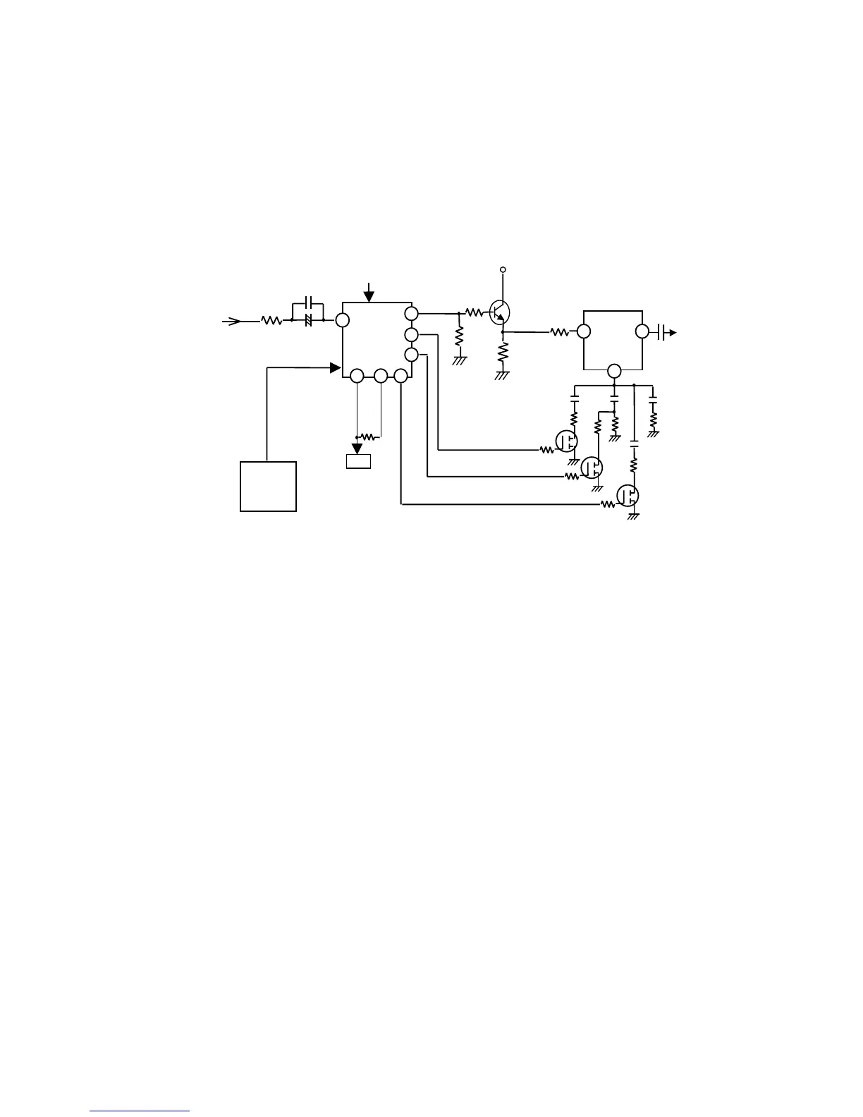
2) Video Signal Amplification Section
The video signal amplification section basically consists of the input section circuit and the amplification
circuit. Each Red(R), Green(G) and Blue(B) video signal circuit is identical to each other, the G circuit being
described below.
The video signal through the input selection circuit is input the amplification circuit. The amplification circuit
is constructed with IC711(Pre-amp), Q711G(buffer), IC721(Output amp).
IC711 controls CONTRAST and R/G/B GAIN with I
2
C BUS by CPU. Only ABL function is controlled by
external DC voltage. IC711 is possible to change gain, it is approx.4.3Vpp after the video adjustment.
The output of IC711 is buffered by Q711G and fed to IC721(Output amp).IC721
’
s gain is fixed approx.15
times.
Rs and Cs connected IC721 pin 13 form emitter peaking. Emitter peaking effect changes 4 levels by Q721G,
Q722G and Q723G.
(Fig 1.2) Video Amplification Circuit
IC711
M52742ASP
PRE-AMP
R736G
IC801
CPU
C712G
C711G