7-30
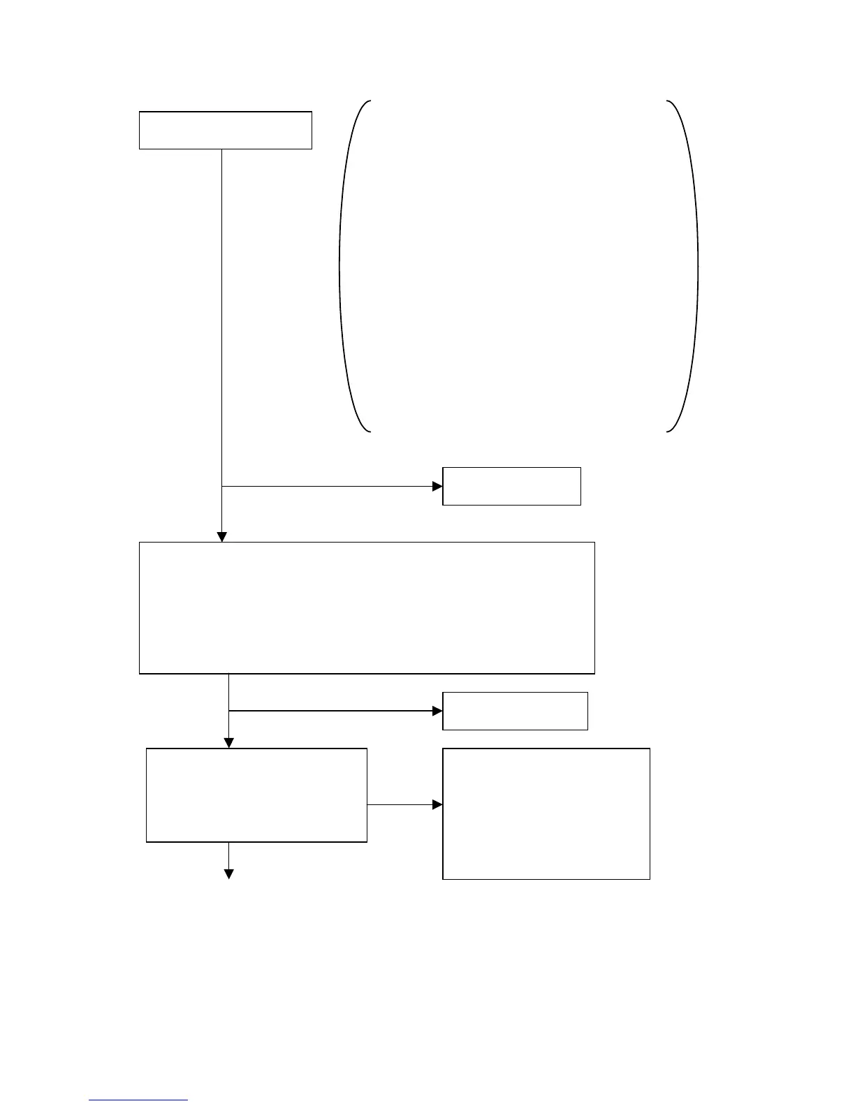
13. SWITCHING REGULATOR CIRCUIT FAILURE
1. Make sure that the voltage of between K 1
pin and 3 pin (GND) is approx. 220V.
2. Make sure that the voltage of between P 3
pin and 5 pin (GND) is approx. 80.2V.
3. Make sure that the voltage of between K 2 pin
and 3 pin(GND) is approx. +14.5V.
4. Make sure that the voltage of between P 6 pin
and 5 pin (GND) is approx. 8.5V.
5. Make sure that the voltage of between K 4 pin
and 3 pin (GND) is approx. -15.6V.
6. Make sure that the voltage of between CR 1
pin and 2 pin (floating GND) is approx. 5.5V.
Passed
Failed
Passed
Failed
Yes
No
CONTINUE
Check the output voltages
Check other circuits
1. Turn off the power switch and wait 1 minute.
2. Disconnect CN-K & P & PM & CR & PS from SW/HV PWB(PWE-571).
3. Short Q673 emitter and Q673 corrector on the SW/HV PWB(PWE-571).
4. Add dummy resistor (2.2KΩ, ±10%,40W) in parallel with R6A1.
5. Add dummy resistor (82Ω, ±10%,2W) in parallel with C6G2.
6. Turn on the power switch and check the output voltages again.
Check other circuits
Either (1) +220V, (2) +14.5V, (3) -
15.6V, (4)+8.5V, (5)+5.5V output is
0V.
+80.2V are normal.
Check the following parts
(1) D6A1, L6A1
(2) D6F1, L6F1, R6F1
(3) D6H1, L6H1, F6H1, ZD6H1
(4) D6G2, R6G1, ZD6G1
(5) D6K1, L6K1, R6K1