7-25
9. RASTER CENTERING CIRCUIT FAILURE
Make certain that the image position is adjusted when the horizontal
centering control(VR581) on the DEF PWB (PWE-568) is used.
NG
The voltage of CN-CR pin1-2 on the DEF PWB (PWE-568)
should be approx. 5.5V.
OK
Q581 or C581 may have failed.
NG
Q581, C581 or VR581 on the DEF PWB (PWE-568), C6K1, C6K2 or
D6K1 on the SW/HV PWB (PWE-571) may have failed.
Adjust the raster centering again.
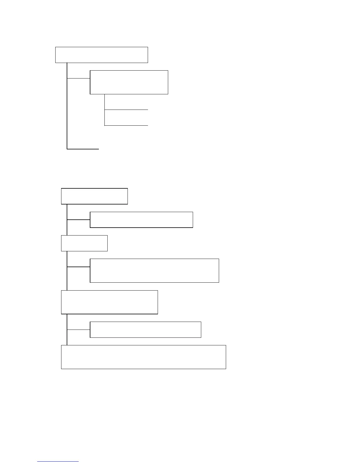
10. RASTER ROTATION ERROR
Check the voltage at IC4J1 pin 10 (+14.5V) and pin 5 (-15.6V) on the DEF
PWB (PWE-568).
NG
OK
Check the voltage at CN-DSA pin 7.
NG
Measure the voltage at IC532 pin 15 on the DEF PWB (PWE-568).
Normally, the voltage varies from approx. 0V to 5V.
NG
OK
Check the raster control operation
Check the raster control
operation voltage.
Check +15 / -15V line
• Check SW REG circuit. (see item 13)
Check +5V line
• LC76K on the VIDEO PWB (PWE-567A) failure.
• CN-ASO,CN-DSA failure.
Check if Z-DY voltage varies by
OSM rotate control.
Digital control circuit failure (see item 12)
• IC4J1 on the DEF PWB (PWE-568) or its ambient circuit failure.
• Z DY (rotation coil ) failure.