8-3
1. VIDEO CIRCUIT
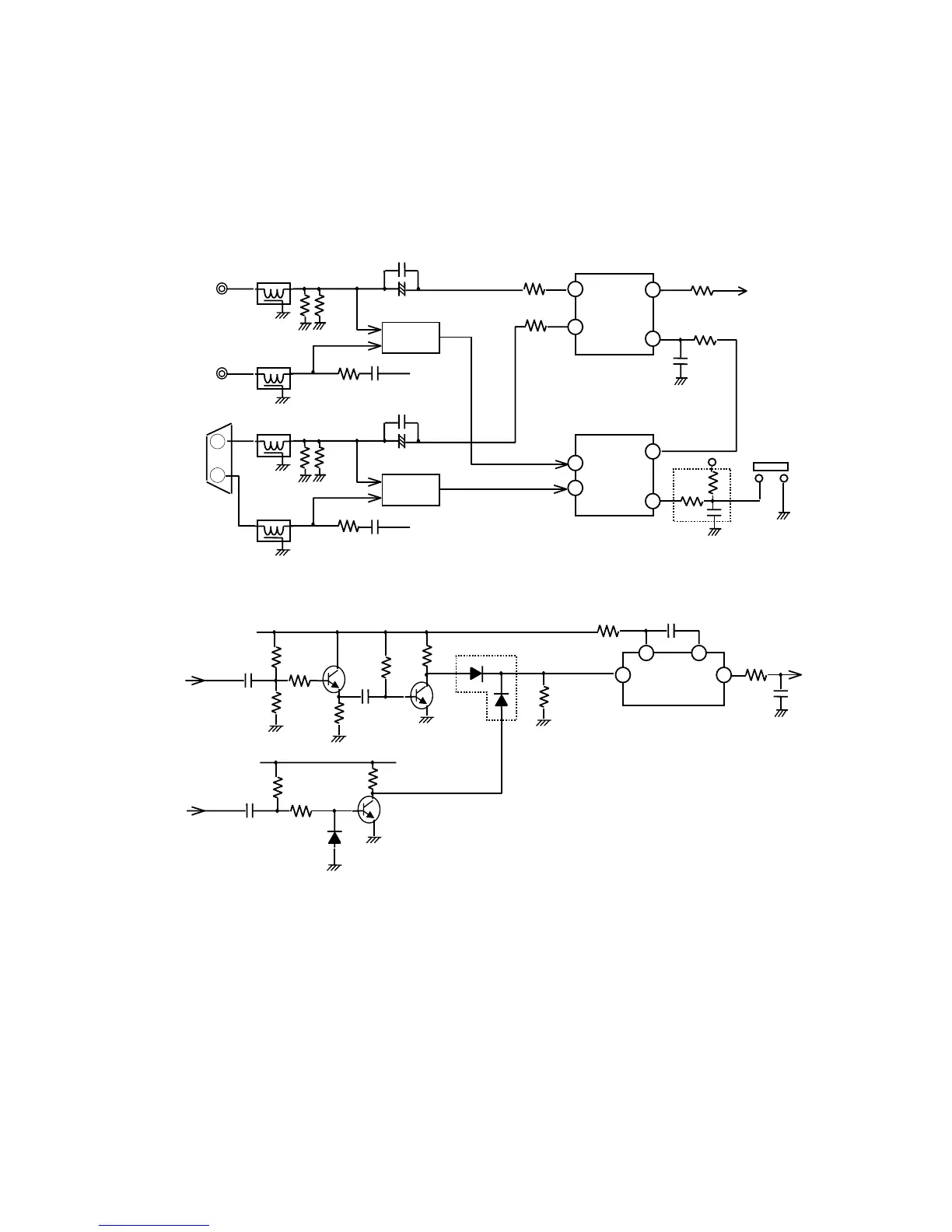
1) Selection of BNC/D-SUB Input
The input selection circuit selects the BNC input or D-SUB input according to the voltage of IC731 pin19 (0V
or 5V). IC731 pin19 voltage changes whenever SW108(momentary switch) is pressed.
CPU detects BNC input or D-SUB input by input signal of Sync On Green and H/C sync. JC-1946UMW’s
user can know by OSM information whether input is BNC or D-SUB. Sync sensor outputs high level when
fH is 1kHz or more, and low level when fH is less than 1kHz.
CPU detects BNC/D-SUB inputs and memories CONTRAST, SHARPNESS and EDGELOCK condition at
each input.
(Fig 1.1.1) Input Selection Circuit (Green channel)
(Fig 1.1.2) Sync Sensor (D-SUB part)
IC731
M52755SP
WIDE BAND
ANALOG
SWITCH