8-6
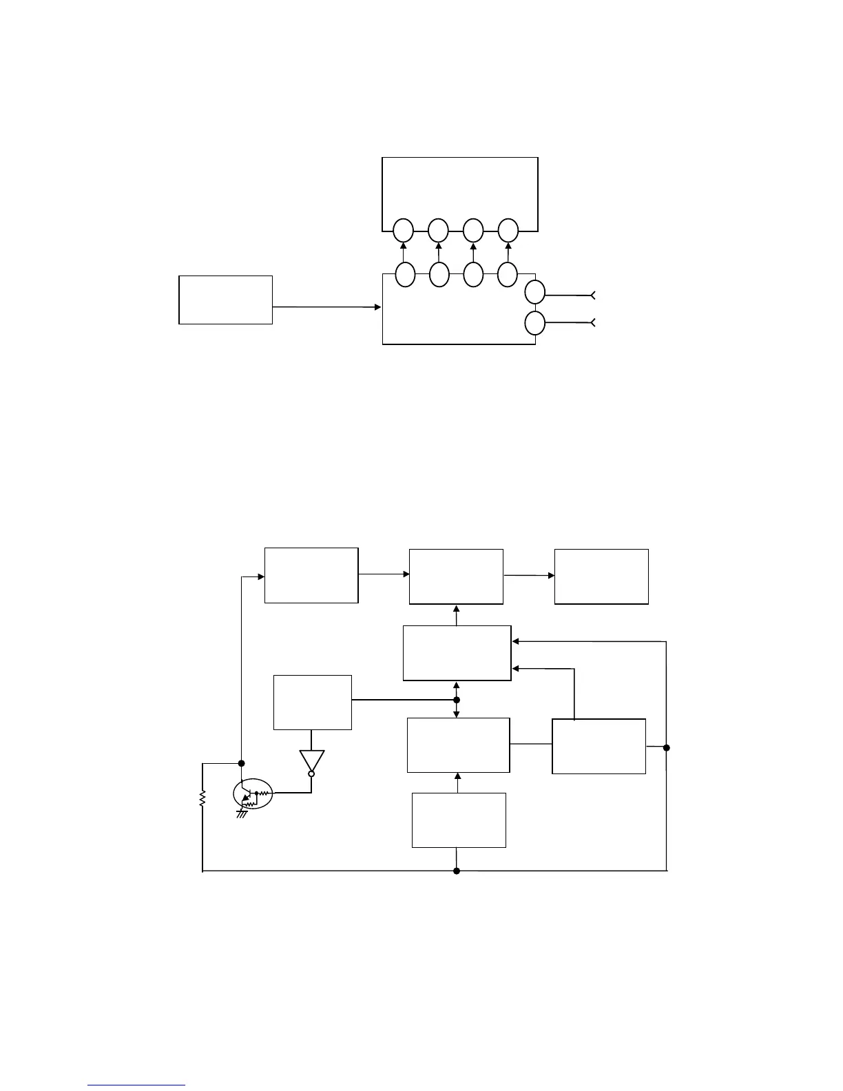
5) On Screen Manager (OSM)
The OSM circuit consists of IC791(OSM controller) and IC711(Pre-amp) which matrix the video signal
and the OSM signal. IC791 receives the display data from IC801(CPU), and the signal outputs R, G, B
and Blanking are fed out of pins 13, 15, 17 and 12 respectively. The OSM signals are mixed with video
signals in IC711(Pre-amp). The OSM screen brightness is controlled by I
2
C BUS from CPU.
(Fig 1.5) On Screen Manager
6) Self Test
There are two ways to activate the self test function.
User mode: power on the monitor while holding down the RESET switch
Factory mode: no H/C sync and SOG of selected input mode
When the self test mode is on, IC801(CPU) make IC501 output H_DRIVE at approx.61.6KHz. Thus the
horizontal deflection circuit and the high voltage circuit are operated at this frequency. And Q797 turn open
by S_BIAS at IC801(CPU) 12pin changed high. Then AFC pulse are fed to IC7A1 to make clamp pulse for
IC711. IC8M1 divide H sync frequency (61.6KHz) by 512,then output V sync(approx.120Hz) to IC501. The
video signal which is all white is generated by IC791, and fed to IC721(Output amp) via IC711(PRE-AMP).
(Fig1.6) Self Test
IC711
M52742ASP
PRE-AMP
IC791
M35070-050FP
OSM CONTROLLER
IC801
CPU
G
13 9 4 1
15 13 17 12
18
19
BLK
R
B
H.SYNC(AFC_T)
V.SYNC(VD_B)
I
2
C
IC791
M35070-050FP
OSM
IC801
CPU
IC501
HE6-0092
DSP(OSC IC)
IC711
M52742ASP
PRE-AMP
IC8M1
BU6483K
AUTO SIZE
IC721
VPS16
OUTPUT-AMP
IC7A1
M52347FP
I/F
DEFLECTION
CIRCUIT
V(PUMP)
AFC(TTL)
CLAMP
PULSE
R/G/B
R/G/B/BLK
VD_SELF
I
2
CBUS
S_BIAS
Q797