7-6
CONTINUE 1 CONTINUE 2
OK
NG
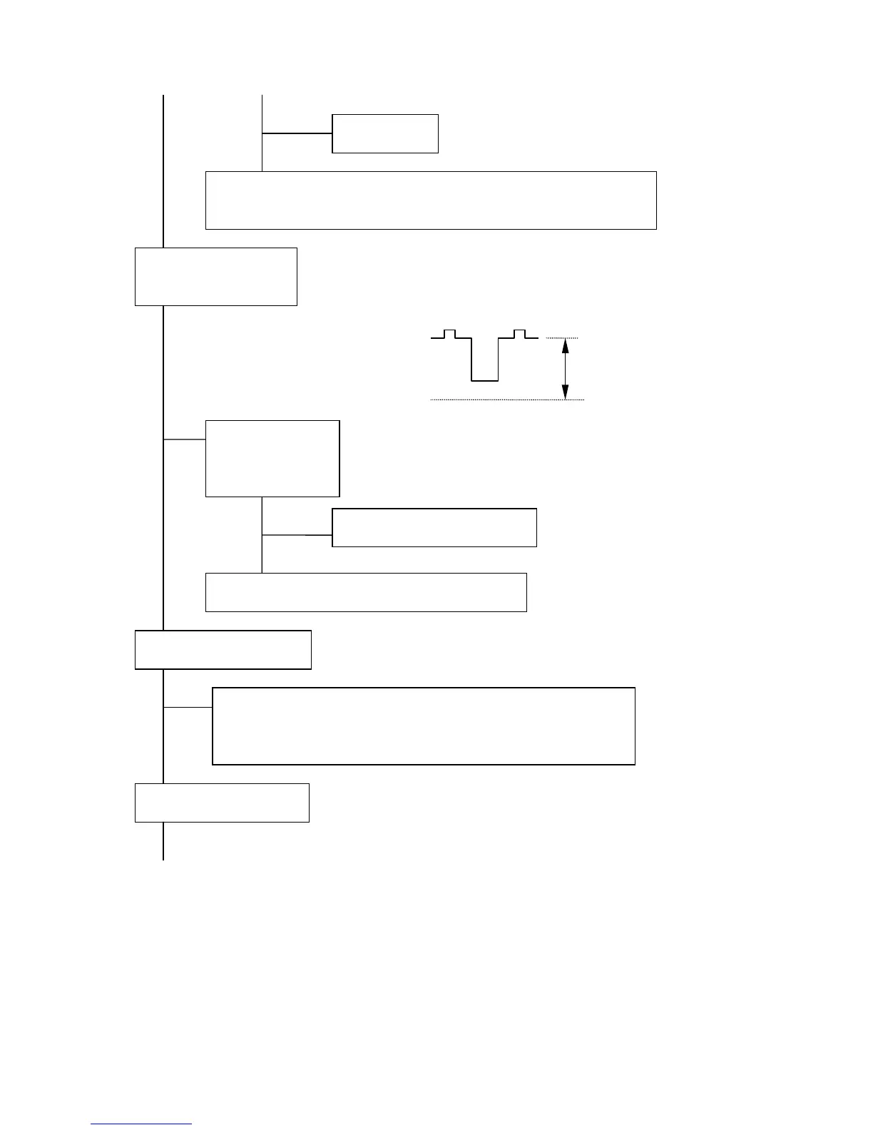
Measure R/G/B cathode voltages at TP-R, TP-G and TP-B on the CRT PWB
(PWE-567C). Normally, the DC voltage is between approx. 80V
DC
and 150V
DC
at point A when BRIGHTNESS is preset. The DC voltage moves 15V or 20V
when BRIGHTNESS changes from min. to max..
NG
Measure the voltage at C747 on the VIDEO PWB (PWB-567A). The
voltage is approx. 220V.
NG
OK
OK
Measure the voltage at TP-G2 on the CRT PWB (PWB-567C). Normally, the
screen voltage is 700±15V
DC
. Adjust 700±5V
DC
if it is different.
NG
OK
Measure the voltage at IC7F1 pin 3 on the CRT PWB (PWE-567C). The
voltage is approx. 6.2V.
CONTINUE
A
GND
IC731 failure.
BNC: LC761R/G/B, C701R/G/B, C702R/G/B or MD701R/G/B failure.
D-SUB: LC762R/G/B, C703R/G/B, C704R/G/B or MD702R/G/B failure.
Check R/G/B cathode
voltage video output
Check the power
supply voltage of
clamp circuit
LC76A, LC76N or CNP failure.
D741 R/G/B, Q741R/G/B, IC742 or IC751 failure.
Check the screen voltage
• R905, C903, C904 or CNCRT on the CRT PWB (PWB-567C),
T5R1 (FBT) on the SW/HV PWB (PWB-571) or screen wire failure.
• Check H OSC/DEF/HV circuit (see item 6)
Check the heater voltage