7-21
CONTINUE1 CONTINUE2 CONTINUE3
NG
NG
OK
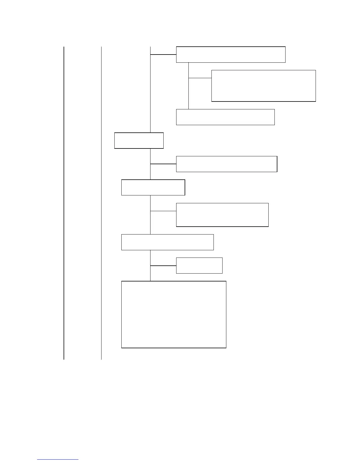
Measure the voltage at C5P1 on the SW/HV PWB (PWE-571).
NG
OK
Check the pulse at Q5R1 gate on the SW/HV PWB
(PWE-571).
OK
NG
Check the pulse at pin 4 of ICD5P1 on
the SW/HV PWB (PWE-571).
NG
OK
CONTINUE1 CONTINUE2
Remove L5R1 and check 80V line again.
• Video amplifier IC721 on the VIDEO
PWB (PWE-567A) failure.
• Check SW REG circuit. (see item 13)
Q5R1 and its ambient circuit failure.
Check 15V line.
Check SW REG circuit. (see item 13)
Check HV drive pulse.
• Q5R1 and ambient circuit failure.
• T5R1 (FBT) failure.
Check the horizontal trigger pulse.
CN-DF Failure.
• Q5F1 and its ambient circuit failure.
• Q5F2 and its ambient circuit failure.
• IC2001 and its ambient circuit failure.
• T5R1 (FBT) failure.
• VR5T1 and its ambient circuit failure.
• ICD5P1 failure.
• R5R3 failure.