NDA-24299 CHAPTER 5
Page 101
Revision 1.0
DATA PROGRAMMING
Assignment of FCH Related Data
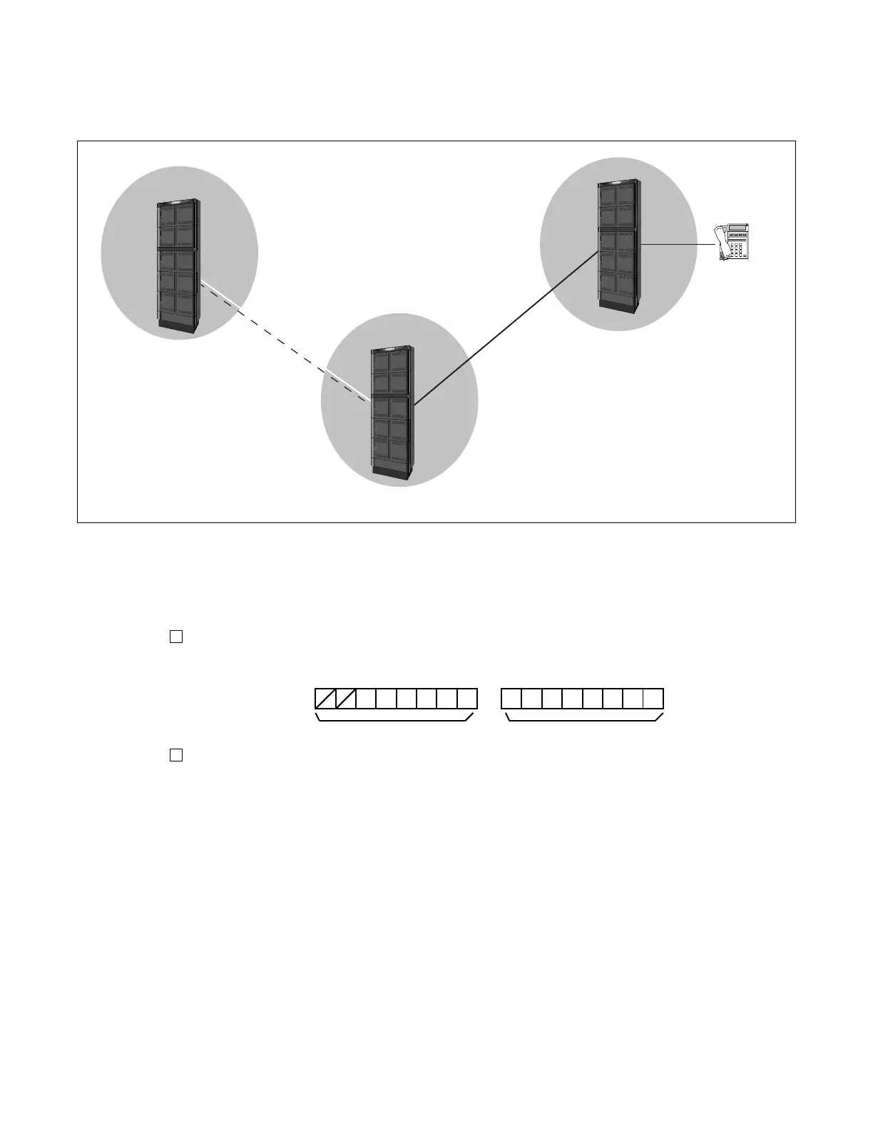
The example data setting is shown using Figure 5-44, on condition that CCIS link data has already been
assigned between FPC2 (PC2) and PC3 nodes.
Figure 5-44 FCCS - CCIS Coexisting Network
The following data setting must be assigned at FPC1 (PC1) node in the example.
STEP 1: ASYD
Assign the OPC (Originating Point Code) within the range 1-16383.
Index 180, 181:
Ex.) OPC=16
Miscellaneous Data
Index 186:
b6 must be assigned as “1 (CCIS is in service).” The remaining data should be determined depending
on the customer’s requirements.
STEP 2: ANPDL/ANPDN
Assign the first digit and NND (Number of Necessary digit) of the LCR access code.
1st DC=7 CI=N (Normal)/H (Hooking)NND=2
STEP 3: ASPAL/ASPAN
Assign the dummy route number to the LCR access code.
ACC=75 SRV=LCRLGRT=Dummy route number
F
C
C
S
FCCS: Fusion Call Control Signal
C
C
I
S
FPC 1
LN
Office Identification Code=75
LGRT=1
CCH=00020
ACC=75
STN: 2000
FPC 2
PC 3
PC 2
PC 1
CCIS: Common Cannel Interoffice Signal
NCN
ffice Identification Code=76
000000 00 000010
b5 b0 b7 b0
Index 181 Index 180
 Loading...