CHAPTER 6 NDA-24299
Page 148
Revision 1.0
POST INSTALLATION TEST
Repair Procedure When LED Indicates Abnormality
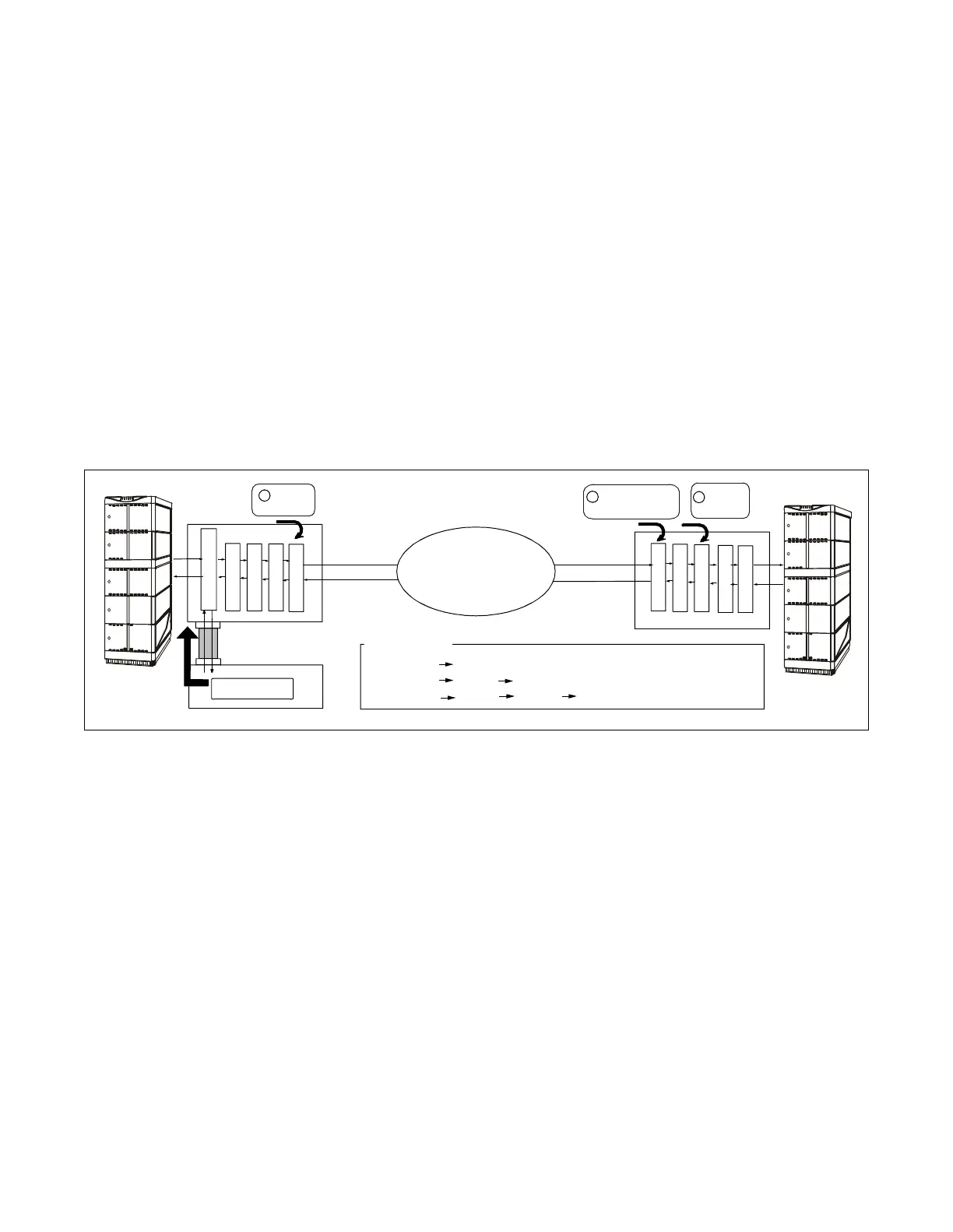
2.2.2 Loopback Point Designation
The DTI card can be set at one of the following loopback points:
1. Internal Loopback
All 24 B-channels sent from the TSW are looped back to the TSW at Interface on the card. At this
time, the adjacent node detects AIS signals. (See ①
in Figure 6-4.)
2. Line Loopback
All 24 B-channels sent from the line are looped back to the line at Line Interface on the card. (See
② in Figure 6-4.)
3. Payload Loopback
All 24 B-channels sent from the line are looped back to the line at Speech Path Control Block on
the card. (See ➂ in Figure 6-4.)
Figure 6-4 Loopback Points of DTI Card
2.3 Test Procedure
STEP 1: Set the MODE switch to 9 (Fusion Link Test) from 8 (standard setting) on the FCH card, and initialize
the circuit card by turning the MB switch ON→OFF. Refer to Figure 6-5.
TDSW Interface
TDSW Interface
PAD
PAD
Speech Path
Control Block
Speech Path
Control Block
Framer
Framer
Line Interface
Line Interface
Payload
loopback
External loopback
(Line Loopback)
Internal
Loopback
FCH card
DTI pkg
1
2
3
N
E
C
N
E
A
X
2
4
0
0
I
M
S
N
E
C
N
E
A
X
2
4
0
0
I
M
S
FUSION
Network
Self-Node
Other Node
front cable
Sending Test
Data Pattern
Analysis Method
Result of (1) NG: Self-Node has errors
Result of (1) OK, (2) NG: Line has errors
Result of (1) OK, (2) OK: (3) NG: Other Node has errors
 Loading...