9. Appendix
123
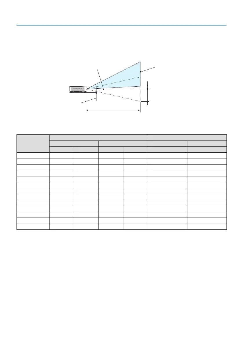
Example of installation on a desktop
The diagram below shows an example of when the projector is used on a desktop.
Horizontal projection position: Equal distance to the left and right from the center of the lens
Vertical projection position: (see table below)
Screen surface
Lower edge of screen with 61.6% V
Measurement +H
Measurement -H
Lower edge of screen with 0% V
Lens center
Approximately 78 to 87 mm
Projection distance L
(NOTE) Height from lens center to lower edge of screen (with tilt feet screwed in)
Screen size
(inches)
Throw distance L Height H
(m) (inches) (m) (inches)
Wide Tele Wide Tele 0%V – 60%V 0%V – 60%V
30 0.77 1.26 30.1 49.5 −20.2 – +4.0 −7.9 – +1.6
40 1.03 1.69 40.6 66.5 −26.9 – +5.4 −10.6 – +2.1
60 1.56 2.55 61.6 100.4 −40.4 – +8.1 −15.9 – +3.2
80 2.10 3.41 82.6 134.3 −53.8 – +10.8 −21.2 – +4.2
90 2.36 3.84 93.1 151.3 −60.6 – +12.1 −23.8 – +4.8
100 2.63 4.27 103.6 168.2 −67.3 – +13.5 −26.5 – +5.3
120 3.16 5.13 124.6 202.1 −80.8 – +16.2 −31.8 – +6.4
150 3.96 6.43 156.1 253.0 −101.0 – +20.2 −39.7 – +7.9
180 4.76 7.72 187.6 303.8 −121.2 – +24.2 −47.7 – +9.5
200 5.30 8.58 208.6 337.8 −134.6 – +26.9 −53.0 – +10.6
250 6.36 10.30 250.5 405.6 −161.5
– +32.3 −63.6 – +12.7
270 7.16 11.59 282.0 456.4 −181.7 – +36.3 −71.5 – +14.3
300 7.96 12.89 313.5 507.3 −201.9 – +40.4 −79.5 – +15.9
 Loading...