viii
Important Information
Clearance for Installing the Projector
Allowampleclearancebetweentheprojectoranditssurroundingsasshownbelow.
Thehightemperatureexhaustcomingoutofthedevicemaybesuckedintothedeviceagain.
AvoidinstallingtheprojectorinaplacewhereairmovementfromtheHVACisdirectedattheprojector.
HeatedairfromtheHVACcanbetakeninbytheprojector'sintakevent.Ifthishappens,thetemperatureinsidethe
projectorwillrisetoohighcausingtheover-temperatureprotectortoautomaticallyturnofftheprojectorspower.
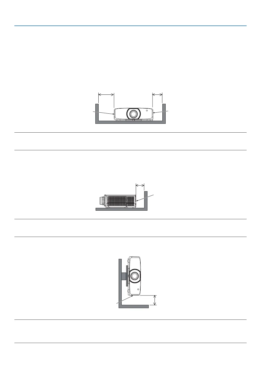
Example 1 – If there are walls on both sides of the projector.
20 cm/7.9" or greater 13 cm/5.1" or greater
Filter cover
(Intake vent)
Lamp cover
NOTE:
The drawing shows the proper clearance required for the left and right of the projector assuming sufficient clearance has been kept
for the front, back and top of the projector.
Example 2 – If there is a wall behind the projector.
10 cm/3.9" or greater
Exhaust vent
NOTE:
The drawing shows the proper clearance required for the back of the projector assuming sufficient clearance has been kept for the
right, left and top of the projector.
Example 3 – In the case of portrait projection.
Filter cover
(Intake vent)
13 cm/5.1" or greater
NOTE:
• Thedrawingshowstheproperclearancerequiredforundertheprojectorassumingsufcientclearancehasbeenkeptforthe
front, rear and top of the projector.
• Seepage150 for an installation example on portrait projection.
 Loading...