© by N&W GLOBAL VENDING S.p.A. 53 10 2009 3325 - 00
acTuaTion Board
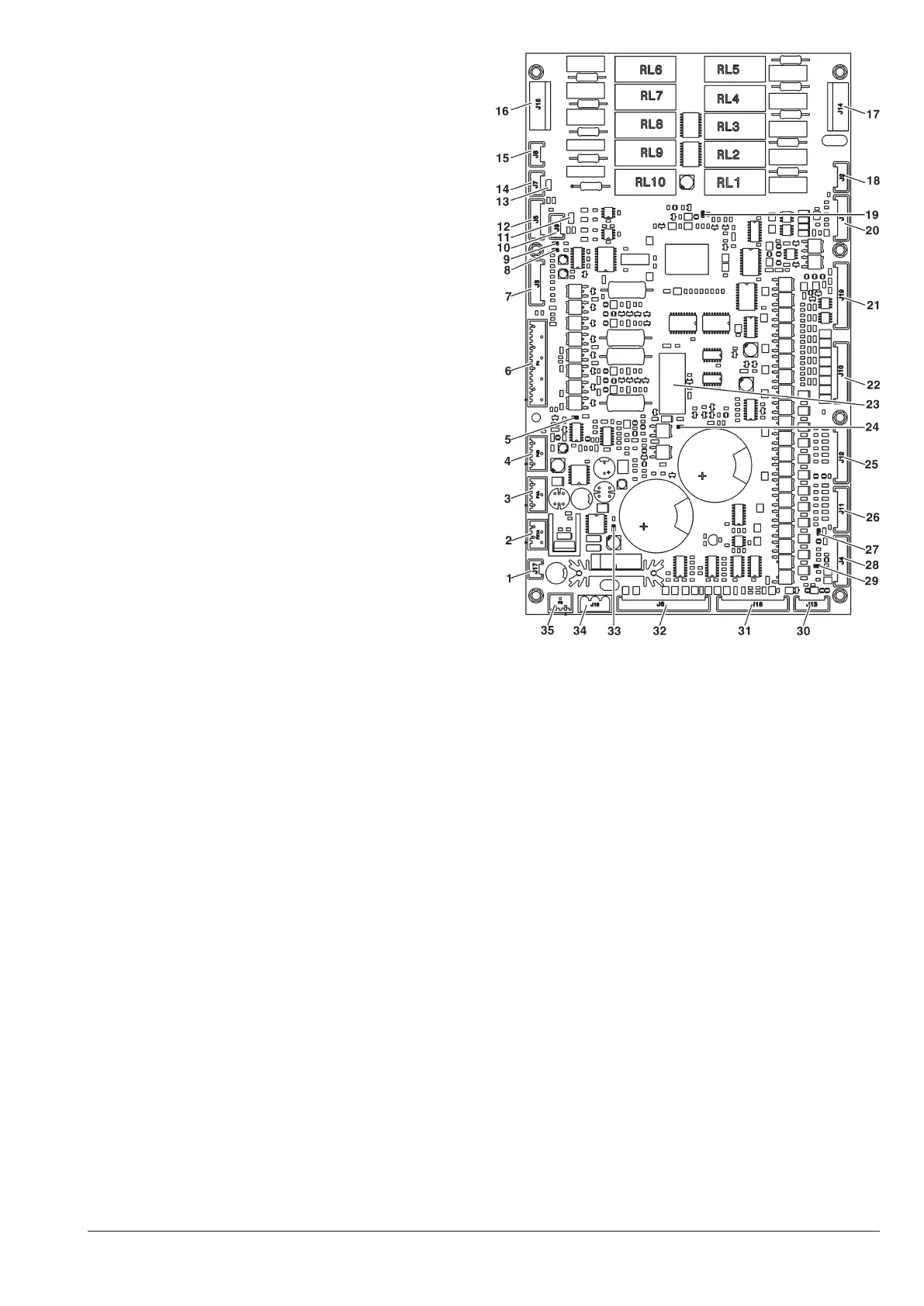
This board (see g. 39) is intended to activate the 230
V~ users through relays and the direct current motors
directly. Moreover, it can manage the signals from the
cams and/or microswitches on the various users. Moreo-
ver, it can control the instant boiler relay. The board is
supplied at 24Vac.
The software intended to manage the board is directly
loaded onto the microprocessor (by means of RS232.
- the green LED 3 (27) is flashing on and off during the
normal operation of the board
- the green LED 6 (33) is signalling that 5 Vdc is applied
- the red LED 4 (19) is on during the reset of the board
- the red LED 2 (8) is signalling the operation status of
the espresso boiler heating element
- the red LED 1 (9) is signalling the operation status of
the instant boiler heating element
- the green LED 8 (29) shows the volumetric counter
pulses (if mounted)
- the green LED 5 (5) is signalling that 34 Vdc is applied
- the green LED 7 (24) is signalling that 34 Vdc is regu-
lated and applied.
insTanT Boiler conTrol relay
this relay is intended to control the trip of the instant
boiler heating element
RELAY FUNCTION (see the wiring diagram)
RL1 = PM
RL2 = MAC 2
RL3 = ESC 2
RL4 = ESC
RL5 = ER
RL6 = MAC
RL7 = EEA
RL8 = Not used
RL9 = MSB
RL10 = MSCB
Fig. 40
1- Steam suction
2- 34 Vdc safety relay coil and door input
3- 34 Vdc power supply to the CPU
4- 34 Vdc power supply to the CPU
5- LEDs
6- Z4000 unit
7- To the relay expansion board (optional)
8- LED 2
9- LED 1
10- Not used
11- Not used
12- Probe and instant boiler relay / probe and boiler and espresso
Triac board
13- JP1 can bus jumper (closed)
14- CAN bus
15- CAN bus
16- 230 V users
17- 230 V users
18- Not used
19- LED 4
20- Not used
21- 24 V input and output
22- MD
23- 34 Vdc safety relay
24- LED 7
25- MF
26- PM
27- LED 3
28- Board programming connector (RS232)
29- LED 8
30- Not used
31- Input
32- Input
33- LED 6
34- 24 Vac power supply
35- Not used