© by N&W GLOBAL VENDING S.p.A. 48 03 2010 3335 00
BOARD funCTIOnS
The C.P.U. board, the actuation board and the glassfront
lighting board are arranged in the slide-in compartment
of payment systems.
Open the slide-in compartment to access the boards.
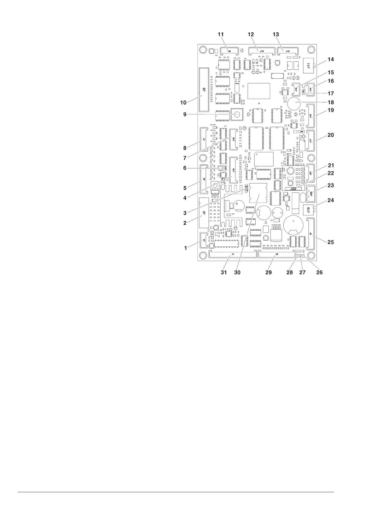
Cpu BOARD
The board is complete with some LEDs that can supply
the following information during the operation:
- the green LED (26) is flashing on and off during the
normal operation of the C.P.U. board;
- the yellow LED (28) will turn on when 5 Vdc is applied;
- the red LED (27) will turn on if the software is reset for -
any reason whatsoever.
The C.P.U. board manages:
numeric selection keyboard -
direct selection keyboard (if available) -
payment system -
the graphical display -
actuation of the cooling unit and sensors -
glassfront lighting -
Fig 39
Temperature probe1-
Validators2-
Battery jumper (2-3)3-
Not used4-
Not used5-
JP4 WDI jumper (closed)6-
Up-key7-
Selection keyboard8-
Programming button9-
Graphical display10-
Not used11-
RS232 serial port12-
EXE/BDV payments13-
MDB payments14-
Can-Bus15-
Can-Bus16-
Can-Bus JP1 jumper (closed)17-
Buzzer18-
Not used19-
Not used20-
Not used21-
RAM data expansion (optional)22-
24Vac (classic only) or 34Vac power supply23-
To the glassfront lighting board24-
Compartment block / lighted path25-
DL3 “RUN” green Led26-
DL2 “RESET” red Led27-
DL1 “+5V” yellow Led28-
To the external programming and OUT/R management button of 29-
the cooling unit
Battery30-
Spiral motors (in the models with spiral trays only)31-