© by N&W GLOBAL VENDING S.p.A. 49 03 2010 3335 00
ACTuATIOn BOARD
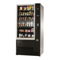
The actuation board (see g. 41) is only arranged in the
models also complete with belt trays.
This board manages:
Motors of spiral trays -
Motors of belt trays -
Dispensing compartment lock device -
Motor-driven dispensing compartment (if available) -
s o f t v e n d - (if available)
The board is complete with some LEDs that can supply
the following information during the operation:
- the red LED (17) will turn on if the software is reset for
any reason whatsoever.
- the green LED (21) will turn on when 5 Vdc is applied;
- the green LED (22) will turn on when 24 Vdc is ap- -
plied;
glASSfROnT lIghTIng BOARD
This board is intended to supply the glassfront lighting
LED’s with direct current for constant brightness.
The board is arranged in the slide-in compartment of
payment systems.
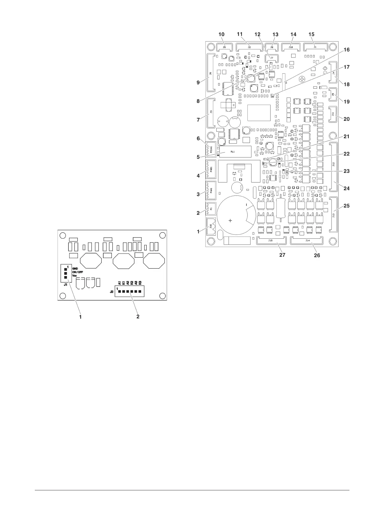
Fig. 40
To the CPU board1-
To the lighting LED boards2-
Fig 41
24Vac power supply1-
Not used2-
CPU 34Vdc board power supply3-
CPU 34Vdc board power supply4-
34Vdc safety relay5-
Safety input relay 6-
LED lighted path7-
Can-bus JP1 jumper (closed)8-
Input / output9-
Not used10-
Actuation board programming11-
Can-bus12-
Can-bus13-
Not used14-
Not used15-
Not used16-
DL2 “RESET” red LED17-
Not used18-
Not used19-
M8 and M9 motor20-
DL3 “+5V” green LED21-
DL4 “+24V” green LED22-
JP3 WDI jumper (closed)23-
M0 - M7 spiral motors and 1 - 7 tray24-
Photocells (if available)25-
Motor and compartment input26-
s o f t v e n d 27- (if available)