11
© by NECTA VENDING SOLUTIONS SpA 0407 239 - 00
MAIN SWITCH
The power supply unit (see Fig. 28) is fitted with a micro-
switch that, when opening the sliding compartment, dis-
connects the power from the machine electrical system,
except from the terminal board supporting the line
cable, the line fuses and from the same switch area.
Before removing the cover from these parts (indicated
with a specific plate) it is necessary to disconnect the
external switch.
The power supply can be reconnected, if necessary, by
inserting the special key supplied with the machine.
All operations which require the machine to be ener-
gised with the door open must be carried out by
qualified personnel who are aware of the specific risks
of such condition.
DISPENSING COMPARTMENT
MANUAL RELEASE
Some models are fitted with a lock device in the dispens-
ing compartment that is released through electric control
when a selection is made (see compartment lock param-
eters).
Should for any reason be necessary to open the compart-
ment without electric power, do as follows:
- remove the last tray;
- remove the anti-theft grille;
- manually operate the lock device.
INTERNAL COMPONENTS
The evaporator assembly mounted on the cabinet shelf
comprises two fans, the evaporator, the air duct and a
water retaining tray placed under the evaporator.
The C.P.U. board (central processing unit) fitted inside the
payment system compartment controls the different func-
tions of the vending machine.
The cooling unit is located in the lower part of the cabinet.
When removing all all covers of the ventilation grille, a
uniform temperature is achieved in the cabinet, se be-
tween 5°C and 20°C.
With the ventilation grille covers fitted, the temperature in
the cabined is diversified between the upper trays (12-
15°C) and the lower trays with the holes on the duct open
(5 -7°C).
The cooling unit is defrosted automatically every 6 hours.
In any case, the timing is programmable.
The power supply unit, mounted in the lower section of the
cabinet, contains the relay card which activates the com-
pressor, the protection fuses and the switch on the pay-
ment system door.
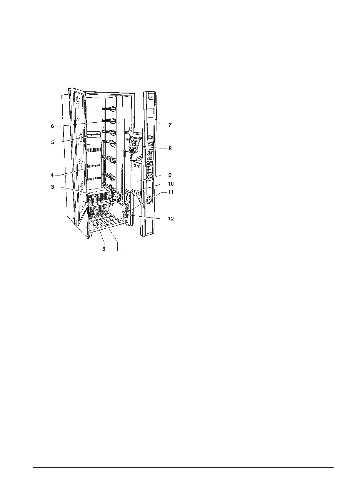
Fig. 15
1 - Product dispensing compartment housing
2 - Cooling unit condenser
3 - Cooling unit evaporator
4 - Cold air flow grilles
5 - Removable grille cover
6 - Tray guides
7 - Removable payment system compartment
8 - C.P.U. board
9 - Coin mechanism support
10 - Product passage photocells
11 - Power supply unit
12 - Payment system compartment door switch