VP1006-200PM-00 OEM ISO Reader Manual version 2.6 / Page 4
See the relevant equipment manual relating to where the VP1006 is to be installed. See also appendix
E, F and G for the different connection possibilities.
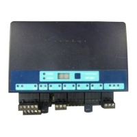
Figure : I/O of the VP1006. The feed motor, input and output connections are shown above as an
example.
Details VP1006 inputs and outputs
Synchronisation for HDX, AC (no plus or minus, cable must be twisted pair)
Motor output or normal output max 3A
Minus for motor output or normal output
Input of motor or normal input
Minus for motor input or normal input
Minus for output (O) and minus input (I)
Antenna with external adjustment
Antenna with no adjustment
Antenna minus (shield of coax cable)
Frequency synchronisation (not used yet)
IMPORTANT : Use power supply with a fused output such as Velos VP2001, VP2002.
Black (-)
Blue (C
h)
Blue/white (C
l)
Shield
Orange (Sync)
Orange/white (Sync)
1,5 mm
2
Communication
0,34 mm
2
Twisted pair shielded
HF Synchronisation
0,34 mm
2