VP1006-200PM-00 OEM ISO Reader Manual version 2.6 / Page 5
Before starting with adjustments first install all components and wiring. Follow the sequence as
indicated in this chapter.
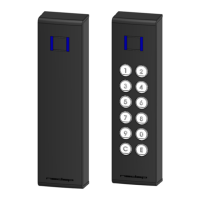
Check if the VP1006 has power after power up. This means 3 green LED’s are on, see figure below.
For more details about the LED indicators see Appendix D.
If LED’s are green, continue with address settings
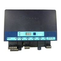
5.2 Communication bus termination jumper
Termination is only used in case of RS485 communication.
When using RS485: at the last VP1006 in the communication
line (bus) the jumper must be set to the other position. Also at
the beginning of the line (computer) termination is required.
For RS232 and CAN always use default jumper position
Check LED “COM” to evaluate the connection to the computer.
 Loading...