Setup
18
Interface/Powerbase Rear Panel
NELLCOR INCORPORATED
INTERFACE/POWERBASE
SERIAL NO.
ELETRICAL RATING
100-120 Vac .3A 50/60 Hz
WARNING
REPLACE FUSE AS MARKED
MADE IN USA NELLCOR INC, PLEASANTON, CA 94588
USE .5A
SLOW BLOW
FUSE ONLY
12
0-10
0-1
0-
100
50-
100
12345678
REFER TO MANUAL
1
2
3
4
5
6
7
8
BAUD
RATE
RS232
FORMAT
ADULT/
NEONATAL
ALARM
ZERO FULL TREND EVENT
PULSE SAT ECG
RATE
SERIAL COMM
DATA
VOLT
S O %
SCALE
a 2
IN/OUT
12345678
33 32 31 29 27 26
25 24 23
22
212019181716
30 28
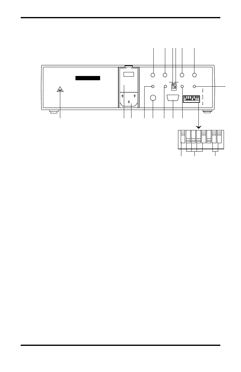
Figure 3: Interface/Powerbase Rear Panel
16. ZERO button: Provides a zero-volt signal on PULSE,
SAT, and RATE analog outputs.
17. FULL button: Provides a full-scale signal on PULSE,
SAT, and RATE analog outputs. (The voltage depends on
VOLT switch setting).
18. SpO2% SCALE switch: Sets the analog output scale for
oxygen saturation at 0–100% or 50%–100%.
19. VOLT switch: Sets the voltage output range for the
analog outputs.
20. TREND button: Initiates a trend memory output sequence.
21. EVENT button: Initiates an event memory output
sequence.
22. ECG IN/OUT connector: Provides an analog ECG output
signal or can be used for an input from an external ECG
monitor.