N1500i FACS Manual
25
Part No. 729-110-053 V.1.03 © 2018 Nelson Stud Welding, Inc. All rights reserved.
3.3.8 Parameters for short cycle procedure
The following parameters are only starting points (
guide values
) which
must
be adjusted to specific application conditions (base material,
workpiece surface condition, weld position, gun type, weld circuit
inductance and
grounding etc.). It is recommended to perform weld
robustness test (current-
time tolerance graph) using the values below as
center points to determine
optimum welding parameters for the
application.
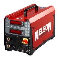
3.3.9 Parameter for drawn arc procedure
The duty cycle limits for the Nelweld N1500i can be seen in the Stud
Weld Rate table below. If the duty cycle is exceeded, and a weld is
attempted, a “Wait” prompt will be displayed. “Wait” will disappear
when the unit is ready for another weld.
If the unit reaches an abnormally high temperature, a failsafe thermal
sensor will protect the unit, prevent welding, and E011 will be displayed
on the front panel. The welder will resume normal operation, and allow
welding, once the temperature has returned to its safe operating range.