1010
1010
10
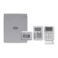
NESS D16 (V4.6) CONTROL PANEL - INSTALLER MANUAL
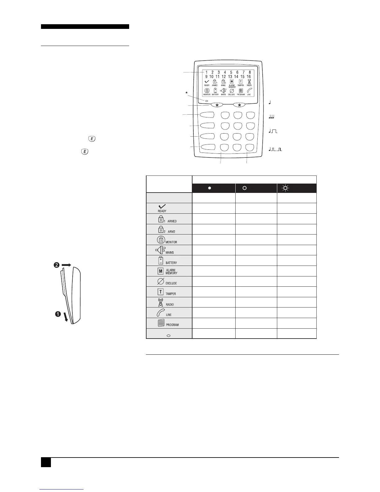
KEYPAD
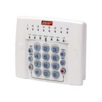
D16 LCD KEYPAD
The Ness LCD keypad provides
important visual and audible
indication of the system status and
is the main interface for controlling
the many powerful features of the
D16 system.
Information is displayed on a large
LCD icon display which is backlit for
easy night viewing.
DISPLAY TEST
To display all the keypad icons
press and hold the
button for at
least 2 seconds. All the icons will
be on whilst the button is held
down.
Display Test can be activated at any
time either in operating mode or any
program mode.
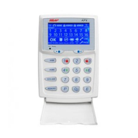
NUMBER OF KEYPADS
Up to 3 LCD keypads can be
connected to the D16.
CABLE LENGTH
The maximum allowable cable
length is 100m (total cable length to
all keypads) .
2
5
8
0
1
4
7
P
3
6
9
E
ARM
MONITOR
EXCLUDE
MEMORY
Not Ready
EACH KEY PRESS
1 beep
VALID ENTRY
3 beeps
ERROR BEEP
1 long beep
MAINS POWER IS OFF
BATTERY IS LOWor
10 beeps
10
BACKLIT LCD
ICON DISPLAY
PANIC BUTTONS
“Not Ready” light
ARM BUTTON
MONITOR BUTTON
EXCLUDE BUTTON
MEMORY BUTTON
KEYPAD BEEPER
PROGRAM BUTTON ENTER BUTTON
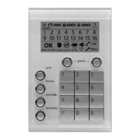
NESS D816 LCD KEYPAD (100-667)
MEMORY MODE - EVENTS INDICATED BY KEYPAD LIGHTS:
LIGHT MEMORY EVENT
Zone lights 1–16 .................. Zone alarm
(no lights) ............................ Panel Disarmed
ARMED ................................. Panel Armed (or Area 1 Armed)
ARM2 .................................... Area 2 Armed
MAINS .................................. Mains power failure
BATTERY .............................. Low Battery
TAMPER ............................... Tamper alarm (Siren cover, panel etc)
EXCLUDE .............................. Panic alarm
LINE ...................................... Telephone line fail
RADIO, EXCLUDE .................. Radio Key Panic alarm
RADIO, BATTERY, ZONE ........ Radio Device battery low, (Device number is indicated by zone lights)
RADIO, BATTERY, ARM ......... Radio Key battery low, (Radio Key number is NOT indicated)
RADIO, TAMPER, ZONE ......... Radio Device tamper alarm (Device number is indicated by zone lights)
RADIO, MONITOR, ZONE ....... Radio Supervision fail (Device number is indicated by zone lights)
KEYPAD INSTALLATION
· Unclip the top half of the keypad housing by
pushing the top clips down with a small
screwdriver and pulling the housing forward.
· Screw the base of the keypad housing to the wall
using the 4 mounting holes provided.
· Bring the 4 connecting wires to the terminal
block on the PCB on the rear of the keypad
housing.
· Connect the wires to the screw terminals as per
the wiring diagram shown in this manual.
· Clip the top half onto the base by first engaging
the bottom clips and swinging the top closed.
Push hard to ensure the clips engage.
· Attach the Zone list label on the inside of the lid.