3535
3535
35
PROGRAMMING
NESS D16 (V4.6) CONTROL PANEL - INSTALLER MANUAL
ZONE SPLIT
Setting this option ON splits the Zone Inputs 1-8 into pairs of zones so that
there are 16 wired zones available.
Zones 1-8 use 2K2 end of line resistors on the Z1-Z8 inputs.
Zones 9-16 use 4K7 end of line resistors on the Z1-Z8 inputs (with Zone 9
connected to the Z1 input etc).
The monitoring resistors must be wired in parallel, making this zone splitting
arrangement suitable for Normal Closed (N.C.) detectors.
PROGRAMMING SEQUENCE:
P68E 1E toggles the option ON and OFF
P68E 1E OFF: No Zone Split (panel has 8 zone inputs)
P68E 1E ON: Zone split enabled (panel has 16 zone inputs)
P68E 1E
PROGRAM MODE LEVEL:
Installer, Remote by PC
FACTORY DEFAULT:
OFF: No zone split
NOTES:
• Zone Split is required when zones 9-16
are used as hardwire zones.
• Zone Split does not have to be enabled to
use zones 9-16 as RADIO zones.
• If Zone 8 is converted to a Keyswitch
Input, then a 2K2 monitoring resistor is
always used and Zone Splitting is not
available on the Z8 input (no Zone8,
Zone16). Zone8, Zone16 are still
available as RADIO ZONES however.
See: Keyswitch Operation, page 24
• N.O. contacts can be used only on zones
1 to 8.
END OF LINE RESISTOR NOTES:
• NESS supplies 1% tolerance metal film
resistors for the end of line termination.
These are accurate value resistors and
they stay accurate long term.
• Avoid using carbon film or 5% tolerance
resistors, especially when zone splitting.
Problems may not become evident until
some time after the installation, due to
resistor aging, moisture or dust build up.
• If a particular zone will not seal, then
check the resistance of BOTH the low
zone and high zone cabling (i.e. if zone 1
will not seal then also check zone 9
wiring). The resistance checks should be
done after removing the cabling from the
D16 terminals and separating into their
individual wires.
• A 2K2 monitored line should measure
between 2100 Ohms minimum and 2400
Ohms maximum.
• A 4K7 monitored line should measure
between 4600 Ohms minimum and 4950
Ohms maximum.
INPUT
11
22
33
44
55
66
77
88
ZONE ZONE
9
10
11
12
13
14
15
16
INPUT TABLE
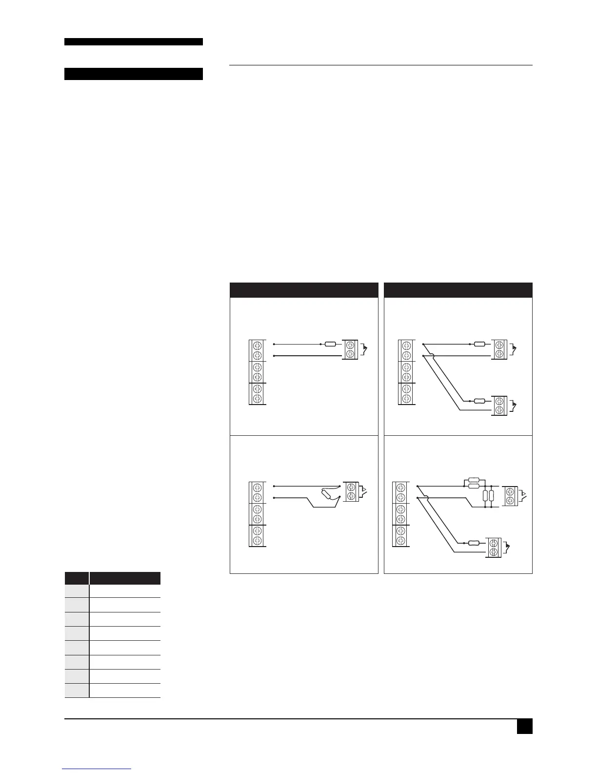
CONNECTION DIAGRAMS
Z1
N.C. Contacts
N.C. Contacts
ZONE 1 DEVICE
ZONE 9 DEVICE
NESS D16
C
2K2
4K7
Z1Z1
N.C. Contacts
N.O. Contacts
ZONE 1 DEVICE
N.O. Contacts
ZONE 1 DEVICE
ZONE 9 DEVICE
NESS D16NESS D16
CC
2 x 2K2
2 x 2K2
4K7
NESS D16
EXAMPLE 3: Normally Closed DevicesEXAMPLE 1: Normally Closed Devices
EXAMPLE 2: Normally Open Devices
EXAMPLE 4:
Normally Open Device Zone 1 ONLY
NORMAL (NO ZONE SPLIT) ZONE SPLIT
2K2
Z1
N.C. Contacts
ZONE 1 DEVICE
C
2K2
Normally Open (N.O.) wiring is possible only on Zones 1 to 8. This is done by
splitting the 2K2 resistor into 2x 1K1 resistors, joining them in series, and then
placing the N.O. contact across one of the 1K1 resistors. (Make a 1K1 resistor
by wiring 2x 2K2 resistors in parallel).
Technical Manuals Online! - http://www.tech-man.com