DescriptionNumber
Recessed Factory Defaults button5
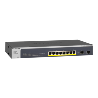
RJ-45 and PoE LEDs that correspond to the individual ports. The upper
LED row functions as the combined speed and activity LED. The bottom
row of LEDs provides the PoE status. See LEDs on page 11.
6
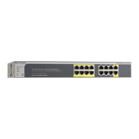
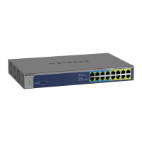
Eight independent 10/100/1000M BASE-T RJ-45 and PoE ports7
1000M SFP Ports8
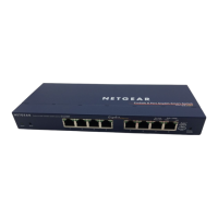
Back Panel
The switch integrates a fixed, internal power supply unit (PSU).
The back panel contains a Kensington™ lock slot and the AC power connector.
Figure 3. GS510TLP back panel
DescriptionNumber
Kensington lock slot1
AC power connector2
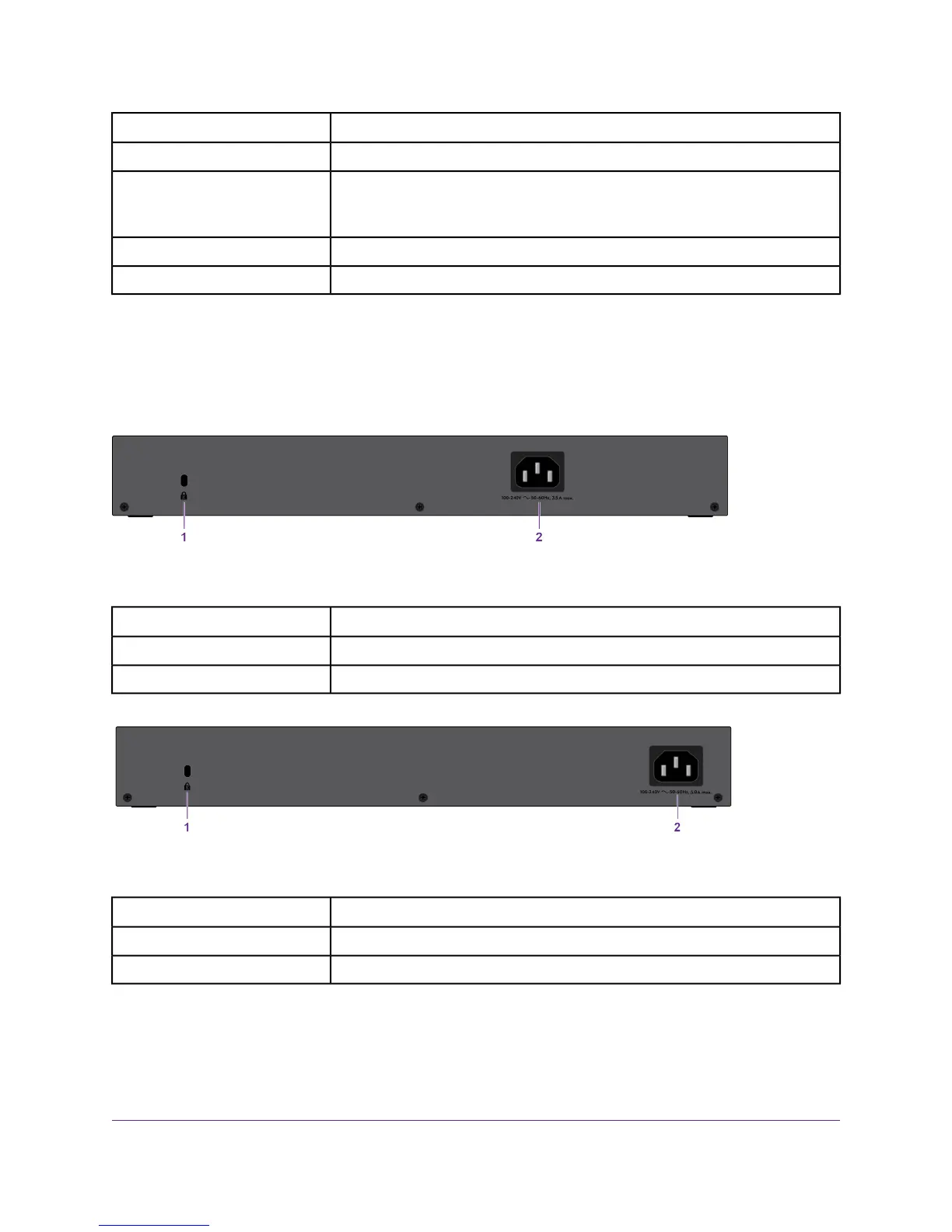
Figure 4. GS510TPP back panel
DescriptionNumber
Kensington lock slot1
AC power connector2
LEDs
This section describes the LED designations of the switch.
Hardware Overview
11
ProSAFE 8-Port Gigabit Smart Managed Switch with PoE+ and 2 SFP Ports
 Loading...