26 | Chapter 4. Installation
GS728TS, GS728TPS, GS752TS, and GS752TPS Smart Switch Hardware Installation Guide
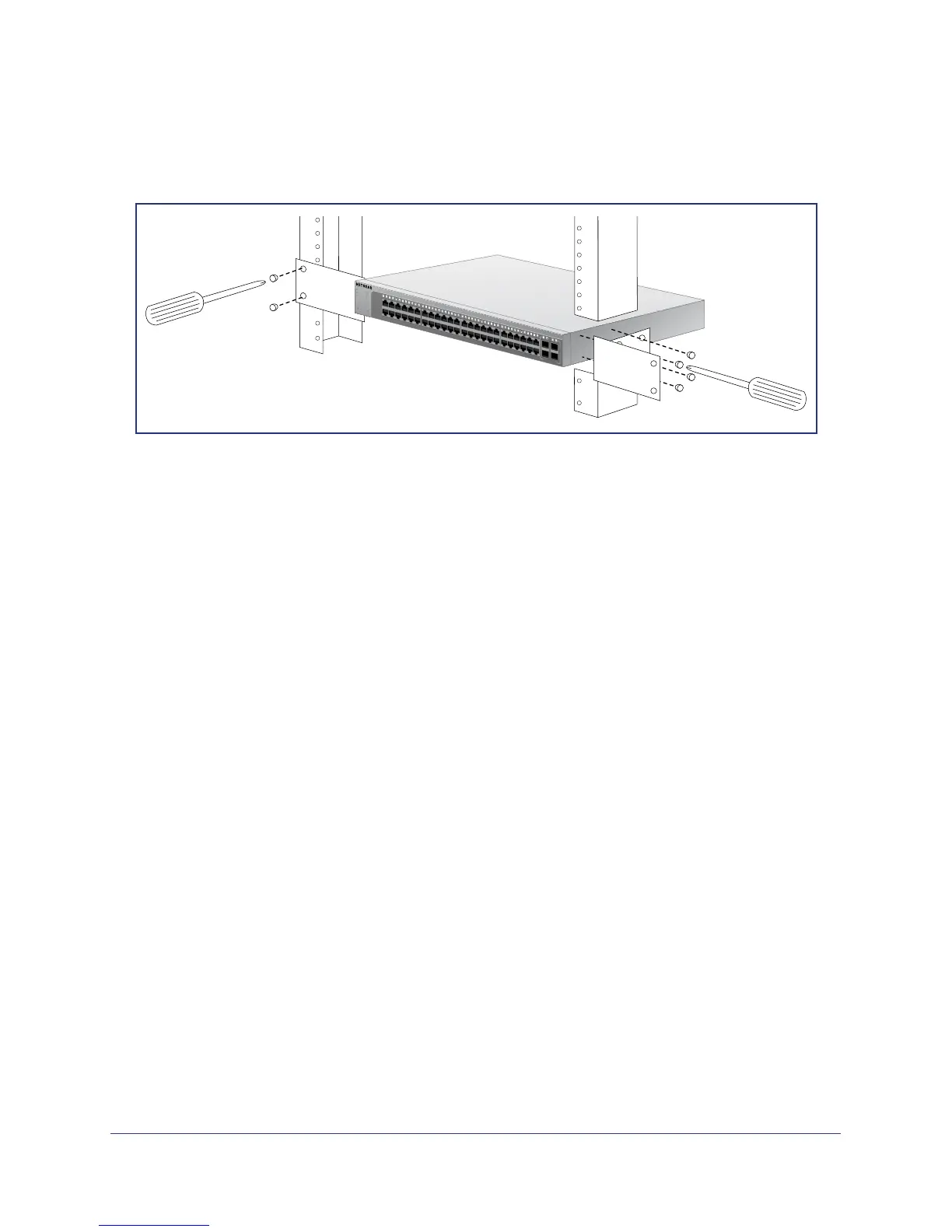
4. Align the mounting holes in the brackets with the holes in the rack, and insert two pan-head
screws with nylon washers through each bracket and into the rack.
5. Tighten the screws with a #2 Phillips screwdriver to secure mounting brackets to the rack.
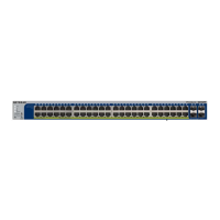
Green=Link at 1G
Yellow=Link at 10/
100M
Power
Reset
ID
Fan
Stack
Master
Factory
Defaults
1
2
3
4
5
6
7
8
9
10
11
13
15
17
19
21
12
22
14
16
18
20
23
25
27
29
31
33
24
34
26
28
30
32
35
37
39
41
43
45
47
36
38
40
42
44
46
48
50F
49F
Green=10G Link
Yellow=1G
Bl
ink=ACT
SFP
+
52F
51F
Link/Act Mode —
Figure 12. Rack Mount
Step 3: Checking the Installation
Before applying power to the switch, perform the following steps:
• Inspect the equipment thoroughly.
• Verify that all cables are installed correctly.
• Check cable routing to make sure cables are not damaged or creating a safety hazard.
• Ensure all equipment is mounted properly and securely.
Step 4: Connecting Devices to the Switch
The following procedure describes how to connect PCs to the switch’s RJ-45 ports. The
GS728TS, GS728TPS, GS752TS, and GS752TPS Smart Switch contains Auto Uplink
technology, which allows the attaching of devices using either straight-through or crossover
cables.

 Loading...