NetGear Print Server Manual
7
Outlooks for PS101 Mini Print Servers
The LEDs that indicate the status of the server, and the printing traffic of the Ethernet are located on
the panels of the Model PS101 Mini Print Sever. It has one 10 BASE-T network port. The port
operates in 10 Mbps and in half-duplex mode when connected to a 10/100Mbps Ethernet network. As
illustrated bellow, it has a power adapter receptacle that accepts a 9V 500mA DC power adapter.
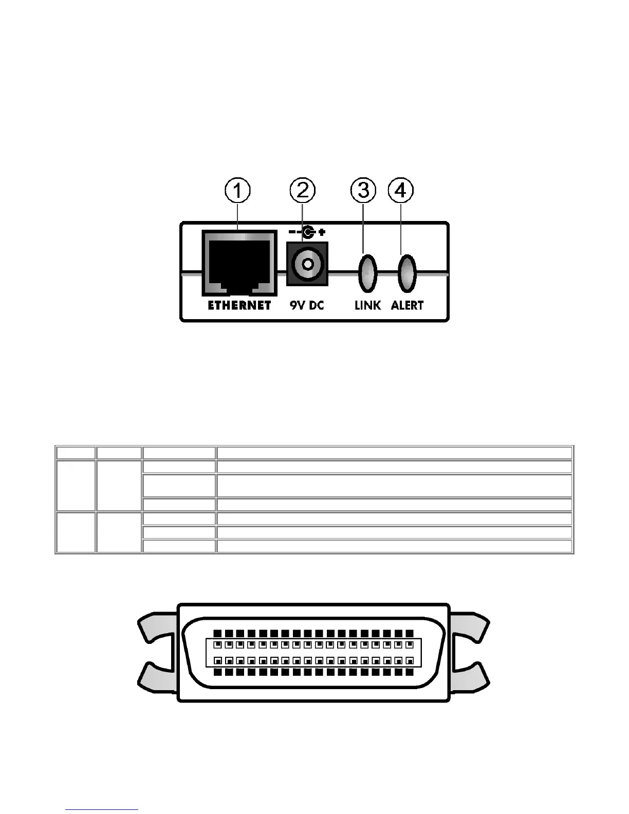
1-1 Panel of the Model PS101 Mini Print Sever
Key:
1 = 10 Base-T ETHERNET port
2 = Power adapter receptacle
3 = LINK LED
4 = ALERT LED
There are 2 LEDs on the panel of the Model PS101 Mini Print Sever. See the table bellow:
LED Descriptions
Label Color Activity Description
Off No ETHERNET connection
On
Powered ON
Operation is normal without data transmitting or receiving from ETHERNET
LINK Green
Blinking Operation is normal with data transmitting or receiving from ETHERNET
Off Operation is normal
On Hardware error
ALERT
Amber
Blinking Upgrading BIOS flash ROM
The parallel port of the Model PS101 Mini Print Sever is a standard Centronics 36 type connecter for
printer. The connecter is as illustrated below.
1-2 Centronics 36 connecter of the Model PS101 Mini Print Sever