Mill Functions
Newall Measurement Systems
28
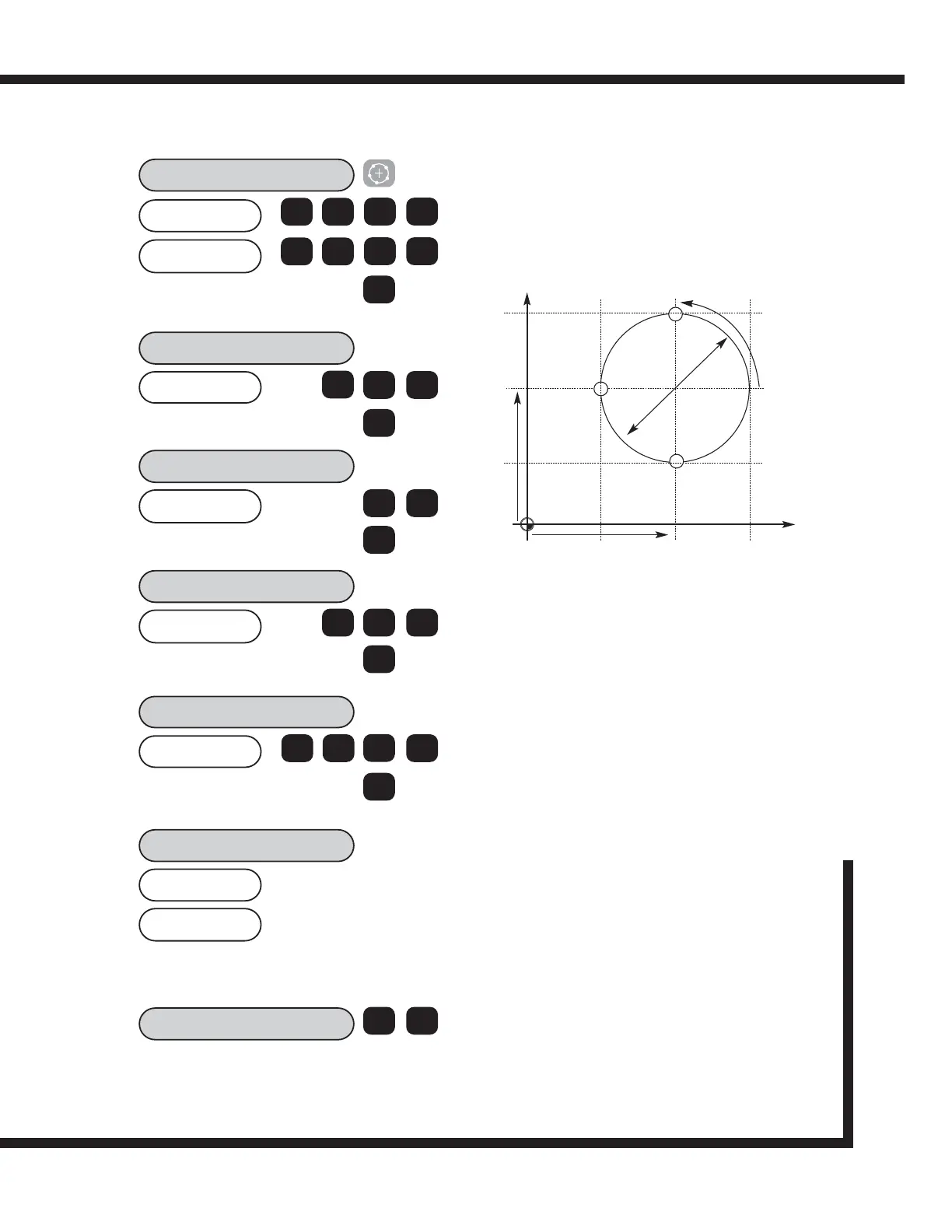
EXAMPLE:
The keystrokes for entering the following bolt hole circle
are shown. X and Y axes are assumed at Absolute Zero.
50.0000
CENTRE?
50.0000
X
Z
The bolt pattern will be calculated from the 3 o'clock
position, counter-clockwise. The starting angle is the angle
from the 3 o'clock position to the first hole. Enter the angle
as a negative value if it is given as clockwise from 3
o'clock.
The ending angle is calculated from the 3 o'clock position
counter-clockwise to the last hole. If the pattern is a
complete circle, enter the same ending angle as starting
angle.
40.0000
DIA?
0
ent
>
3
NO HOLES
3
ent
>
90.000
ST ANG?
0
ent
>
270.000
END ANG?
7
ent
>
-50.000
HOLE 1
>
-70.000
9
2
Position the X and Y axes until both displays
read Zero. This is the first hole location.
HOLE 2
< >
Use the arrow keys to display co-ordinates for
subsequent holes in the routine. Work to zero for each
hole location.
X
Y
90
O
50
50
0
0
70
30
30 70
D 40.0
(50,70)
(50,30)
(30,50)
NOTE: The 2 axes mill operations are similar to the 3
axes version except that the PCD is not plane
selectable.
0
ent
ent
5
0
5
0
4
NOTE:
The numbers appear as negative numbers because the
operator works to 0,0. According to the above drawing,
the first hole is in a positive position for both X and Y.
Therefore, the display will count up to zero when the axes
are moved. If these numbers do not appear, exit the PCD
function and check the axes readings in X and Y. You will
find that the Hole 1 dimensions are the sum of the
absolute positions plus the calculated positions. The hole
locations will always reference 0,0.