M94011A
Oriel
®
LCS-100
TM
Small Area Sol1A
- 22 -
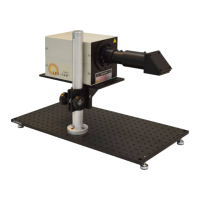
6.2 MOUNTING OPTIONS
The preferred mounting configuration for the illuminator is mounted to an optical table or breadboard
type of mount plate using the Newport Model 75 Mounting Rod. This rod has 4 mount holes that are
spaced to be compatible with inch and metric (25mm) holes. This rod provides the quickest approach
to fine-tune the height while maintaining rotational and planar alignment with the work plane.
The 6” x 12” (152.4 x 304.8mm) integral baseplate has 1/4 - 20 mounting holes at the corners, spaced
5” x 11”. These can be used to mount fixed length posts such as type SP-6, which may then be
mounted within post holders such as type VPH-6, to provide height adjustment. If fixed posts are
used, then it is recommended to adjust the target device (test cell) height, to provide the Irradiance
adjustment. See Figures 18 and 19 for mounting dimension detail drawings.
For upward or side directing applications, the integral baseplate can be bolted to an inch or metric
table. Use the 1/16 hex wrench to loosen and turn the 90
° beam turner. Use a 90° block against the
side of its housing to square it up before retightening. For forward directing of the beam, the beam
turner may be removed (working distance from the tube end reference plane will then be 2.5” more). A
71260 Filter Holder may be used at this optical location for additional external filters. Use extra care in
these configurations to prevent eye damage.
For proper operation, the 94011A(-ES) is to be mounted in a preferred orientation such that its
electrode axis is within 15
° of horizontal. This is important for the lamp life, as well as for proper
airflow and thermal control.
Figure 18: 94011A Dimensions
W.D.
 Loading...