Product Manual, Issue 8 CMS100
www.nexo.comPage 10
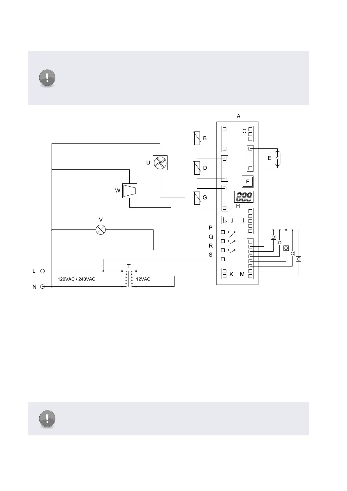
1.7 Wiring diagram
Note
To remove the potential for damage occurring to, and the potential for failure of,
the crimped connection on the mating half of terminals 1 to 4 of the CMS100 Nexo
controller it is recommended that only right angle insulated 6.3mm tab connectors,
complete with strain relief, are used to terminate these cables. Use of straight
connectors may exert excessive pressure on to that connector.
A - Controller I - Modem interface R - Lights out
B - Appliance sensor J - Motion sensor S - Line in
C - RMD K - 12VAC T - Transformer
D - Evaporator sensor L - Live U - Evaporator fan
E - Door switch N - Neutral V - Lights
F - RJ45 Port M - Stock / product sensor W - Compressor
G - Condenser sensor P - Fan out
H - Display Q - Compressor out
Note
An additional input has been inserted between 12AV and Auxiliary inputs. The order
does vary to Elstat’s ems55adv models.