Product Manual, Issue 8 CMS100
www.nexo.comPage 16
The alignment of the door switch and activator is critical for the correct operation of the door switch. The
table details alignment tolerances.
Alignment Dimensions Notes
X Horizontal
0mm (0in)
+/- 20mm (0.7in)
Measured when the door is closed and the gap
(z-dimension) is correct.
Y Vertical
0mm (0in)
+/- 10mm (0.4in)
Measured when the door is closed and the gap
(z-dimension) is correct.
Z Gap
0mm (0in) to 5mm (0.2in)
+/- 2mm (0.07in)
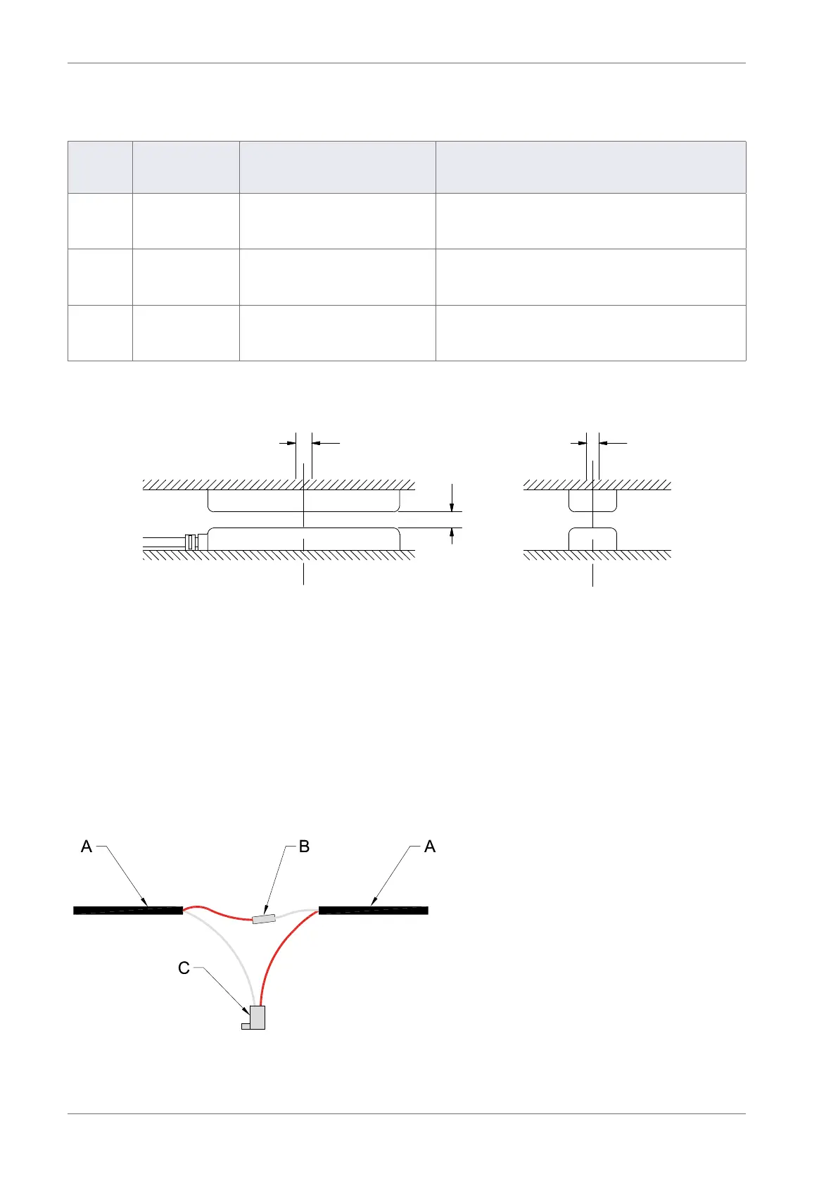
The diagram below shows the horizontal, vertical, and gap alignment between the door switch and the
activator for open and closed doors.
Z
X Y
To mount door switches on double-door coolers, two door switches must be connected in series. Connect
two door switches in series as follows:
` Remove the two wires from one of the connectors. Be careful not to damage the terminals.
` Remove the white wire from the second connector. Again, be careful not to damage the
terminal.
` Insert the white wire of the rst cable into the connector of the second cable ensuring that the
terminal is in the correct orientation.
` Connect the red wire from the rst cable and the white wire from the second cable together
using a butt splice or similar.
The image below shows two door switches connected in series.
A - Door switch cables
B - Cable connector
C - Molex connector