https://reference.digilentinc.com/reference/programmable-logic/nexys-a7/reference-manual 17/30
Modern VGA displays can accommodate different resolutions, and
a VGA controller circuit dictates the resolution by producing
timing signals to control the raster patterns. The controller must
produce synchronizing pulses at 3.3V (or 5V) to set the frequency
at which current flows through the deflection coils, and it must
ensure that video data is applied to the electron guns at the correct
time. Raster video displays define a number of “rows” that
corresponds to the number of horizontal passes the cathode makes
over the display area, and a number of “columns” that corresponds
to an area on each row that is assigned to one “picture element,” or
pixel. Typical displays use from 240 to 1200 rows and from 320 to
1600 columns. The overall size of a display and the number of
rows and columns determines the size of each pixel.
(https://reference.digilentinc.com/_detail/reference/programmable-logic/nexys-a7/n4n.png?id=reference%3Aprogrammable-logic%3Anexys-
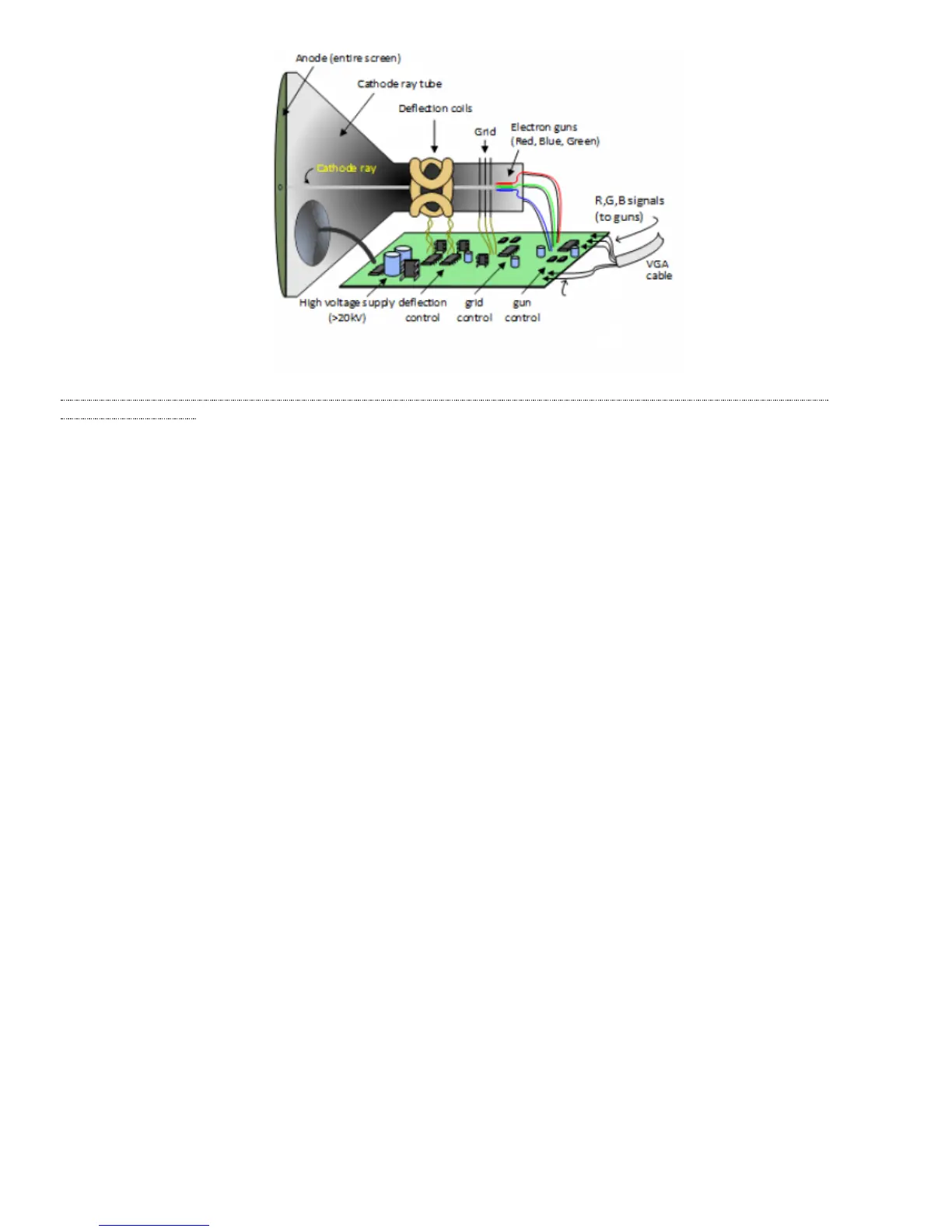
a7%3Areference-manual) Figure 8.1.1 Color CRT Display
Electron beams emanate from “electron guns,” which are finely-pointed heated cathodes placed in close proximity to a positively charged
annular plate called a “grid.” The electrostatic force imposed by the grid pulls rays of energized electrons from the cathodes, and those rays
are fed by the current that flows into the cathodes. These particle rays are initially accelerated towards the grid, but they soon fall under the
influence of the much larger electrostatic force that results from the entire phosphor-coated display surface of the CRT being charged to
20kV (or more). The rays are focused to a fine beam as they pass through the center of the grids, and then they accelerate to impact on the
phosphor-coated display surface. The phosphor surface glows brightly at the impact point, and it continues to glow for several hundred
microseconds after the beam is removed. The larger the current fed into the cathode, the brighter the phosphor will glow.
Between the grid and the display surface, the beam passes through the neck of the CRT where two coils of wire produce orthogonal
electromagnetic fields. Because cathode rays are composed of charged particles (electrons), they can be deflected by these magnetic fields.
Current waveforms are passed through the coils to produce magnetic fields that interact with the cathode rays and cause them to transverse
the display surface in a “raster” pattern, horizontally from left to right and vertically from top to bottom, as shown in Figure 8.1.2. As the
cathode ray moves over the surface of the display, the current sent to the electron guns can be increased or decreased to change the
brightness of the display at the cathode ray impact point.
Information is only displayed when the beam is moving in the “forward” direction (left to right and top to bottom), and not during the time
the beam is reset back to the left or top edge of the display. Much of the potential display time is therefore lost in “blanking” periods when
the beam is reset and stabilized to begin a new horizontal or vertical display pass. The size of the beams, the frequency at which the beam
can be traced across the display, and the frequency at which the electron beam can be modulated determine the display resolution.
Video data typically comes from a video refresh memory; with one
or more bytes assigned to each pixel location (the Nexys A7 uses
12 bits per pixel). The controller must index into video memory as
the beams move across the display, and retrieve and apply video
data to the display at precisely the time the electron beam is
moving across a given pixel.
A VGA controller circuit must generate the HS and VS timings
signals and coordinate the delivery of video data based on the pixel
clock. The pixel clock defines the time available to display one
 Loading...