https://reference.digilentinc.com/reference/programmable-logic/nexys-a7/reference-manual 5/30
(https://reference.digilentinc.com/_detail/reference/programmable-logic/nexys-a7/nexys-a7-callout.png?id=reference%3Aprogrammable-
logic%3Anexys-a7%3Areference-manual)
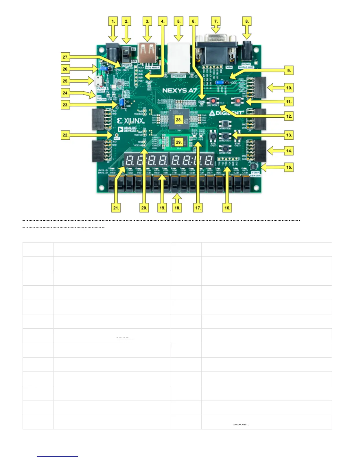
Figure 1. Nexys A7 Feature Callout
Callout Component Description Callout Component Description
1 Power jack 16 JTAG port for (optional) external cable
2 Power switch 17 Tri-color (RGB) LEDs
3 USB host connector 18 Slide switches (16)
4 PIC24 programming port (factory use) 19 LEDs (16)
5 Ethernet connector 20 Power supply test point(s)
6 FPGA programming done LED () 21 Eight digit 7-seg display
7 VGA connector 22 Microphone
8 Audio connector 23 External configuration jumper (SD / USB)
9 Programming mode jumper 24 MicroSD card slot
10 Analog signal Pmod port (XADC) 25 Shared UART/ JTAG USB port
11 FPGA configuration reset button 26 Power select jumper and battery header
12 CPU reset button (for soft cores) 27 Power-good LED ()