WF1945B 1-3
1.2 Operating principles
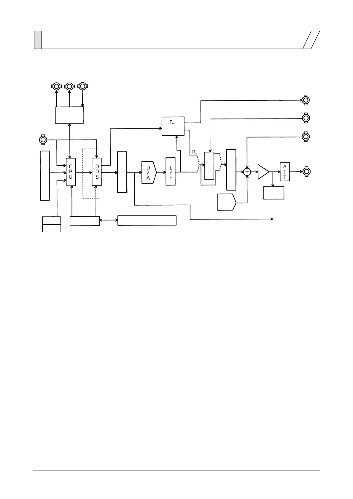
Block diagram
USB
Display and panel key
Amplitude control
occurrence
Others
TRIG/
SWEEP
IN
GPIB
D/A
LPF
DDS
CPU
ATT
Clock
Offset
D/A
SYNC OUT
16bit
16bit
FUNCTION
OUT
Over level
Detector
15bit
AM IN
ADD IN
Isolation
Waveform memory
Sweep
input/output
Digital output
Sync transfer input/output
Multiplier
z The CPU conducts analog control for display, panel keys, remote control (GPIB, USB), DDS,
amplitude and DC offset. Sweep input/output is also controlled for sweep internal/external
modulation.
z The clock generator produces DDS reference and CPU clock signals.
z An isolation circuit between the CPU and DDS provides floating functions.
z The DDS (Direct Digital Synthesizer) uses an original LSI device and generates digital data of
the setting frequency.
z The waveform memory converts digital data from the DDS into standard or arbitrary waveform
data. Waveform data are set from the CPU.
z The digital to analog (D/A) converter produces an analog signal from the resulting waveform
data.
z The lowpass filter (LPF) smoothes the stepped D/A output signal.
z Amplitude control is set by the gain control. DC offset is produced by the offset D/A converter
and the output amplifier adds and amplifies the output signal.
z The attenuator (ATT) selects the output range by 1/10 attenuation on/off.