3.2 Input and output connections
WF1945B 3-15
Avoid shorting the output or applying an external signal. The unit can be damaged.
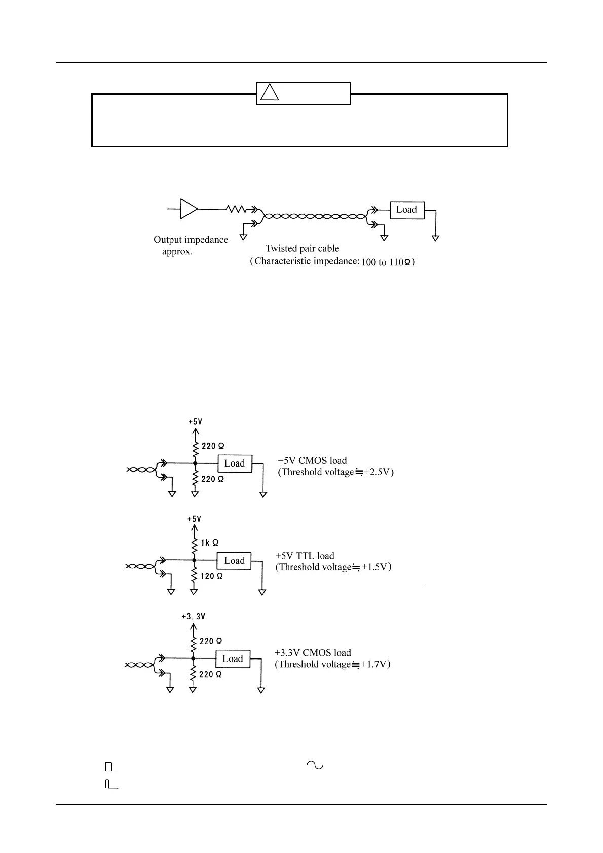
・Accessory cable connection example 1
Since the sending impedance and transmission line characteristic impedance is nearly matching, a
comparatively good waveform can be obtained even with an open load.
・
Accessory cable connection example 2
Even better waveform quality can be obtained by terminating at 110 to 120 Ω. In this case, the
amplitude at the load end is about 1/2 that at the output end.
This response can be utilized to apply a suitable voltage to even a low operating voltage CMOS. But
in this case, do not set to high impedance with the output control line. Circuit damage can occur with
a CMOS device.
・
Digital output is undefined when the oscillation mode is NOISE or DC.
・Except for the following cases, data corresponding to the waveform (FUNCTION) is output as digital
output:
(duty 50% fixed): Data corresponding to is output.
(variable duty): Data to be output is undefined.
! CAUTION
100Ω
115Ω